Electronic component separator and method for producing the same

a technology of electronic components and separators, which is applied in the direction of cell components, cell component details, electrochemical generators, etc., can solve the problems of affecting the ability of the separator, reducing operability and yield in the production process, and affecting the mechanical strength. , to achieve the effect of excellent short-circuiting resistance, excellent workability and high reliability

Inactive Publication Date: 2005-09-22
TOMOEGAWA PAPER CO LTD
View PDF11 Cites 124 Cited by
  • Summary
  • Abstract
  • Description
  • Claims
  • Application Information

AI Technical Summary

Benefits of technology

[0064] The electronic component separator proposed by the present invention maintains various practical characteristics at desirable levels, undergoes minimal heat shrinkage in the event of overheating, and offers high reliability and excellent workability. Therefore, the electronic component separator proposed by the present invention exhibits excellent short-circuiting resistance, low impedance and high heat resistance when used in electronic components such as lithium ion secondary batteries, polymer lithium secondary batteries, lithium metal batteries, aluminum electrolytic capacitors and electric double-layer capacitors, and can therefore be used favorably in the designs of these electronic components. In particular, the porous base of the electronic component separator proposed by the present invention offers excellent dimensional stability under heat and is thus capable of reliably adding dimensional stability under heat to the separator. This feature is particularly suitable for use in large lithium batteries and electric double-layer capacitors requiring higher heat resistance.

Problems solved by technology

However, reducing the film thickness of conventional separators will cause minor short-circuiting between the positive and negative electrodes or affect the separator's ability to retain a sufficient amount of driving electrolyte solution needed to drive the electronic component.
In addition, mechanical strength will also drop, which will lead to various problems such as lower operability and yield in the production process and an eventual drop in product reliability.
If porosity is reduced, however, internal resistance will increase to levels at which the separator will no longer satisfy the high-function requirements.
However, onboard devices for automobiles have a relatively high operating temperature range and are also subject to temperature rise when used continuously at high rates.
Polyolefin resin separators, which represent the mainstream separator specification at the present, are unable to meet this requirement.
Therefore, these separators are prone to shrinkage in a high-temperature environment.
However, segregated filler grains detach and drop more easily, particularly during their handling in the production process, etc.
As a result, areas from which the filler grains have detached / dropped are likely to become coating defects and lead to pinholes or other separator defects.
Additionally, a non-woven fabric made with fibers of low melting points shrinks more easily and may pose other problems.
However, this patent literature gives no considerations to the diameter of through pores, distance between adjacent through pores, separator film thickness, and so on.
A microporous polyolefin resin film such as the one proposed in this patent literature is inherently prone to some degree of shrinkage in a meltdown temperature range corresponding to or above the shutdown temperature.
As a result, this microporous polyolefin resin film easily causes short-circuiting between the electrodes.

Method used


Image

  • Electronic component separator and method for producing the same
  • Electronic component separator and method for producing the same
  • Electronic component separator and method for producing the same

Examples


example 1

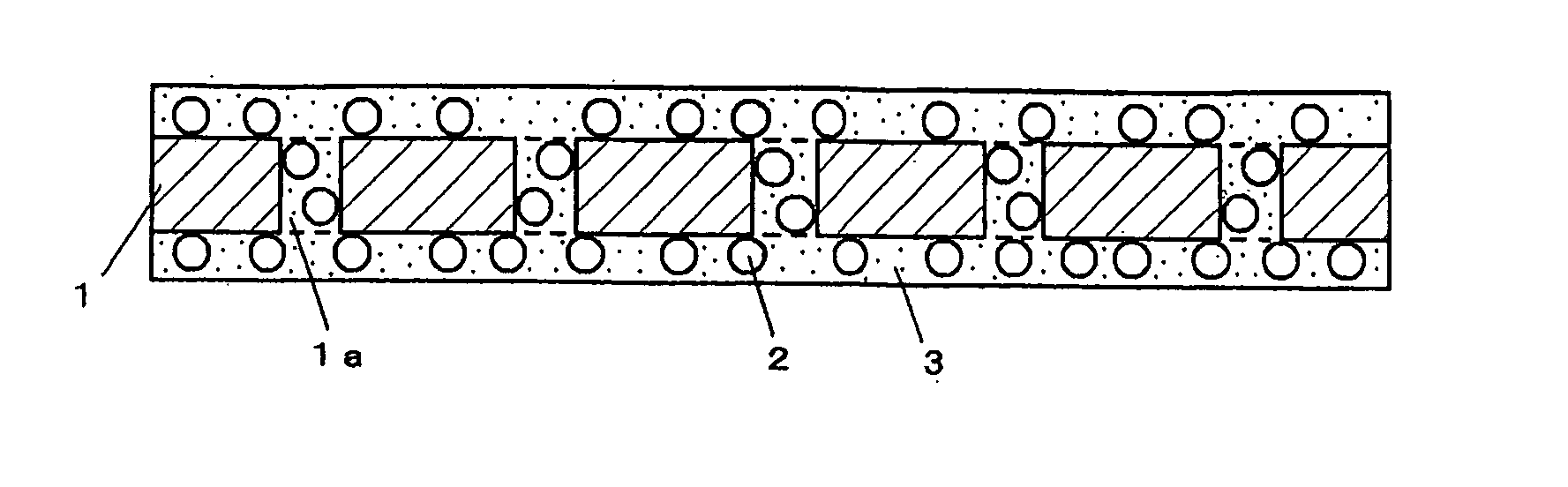
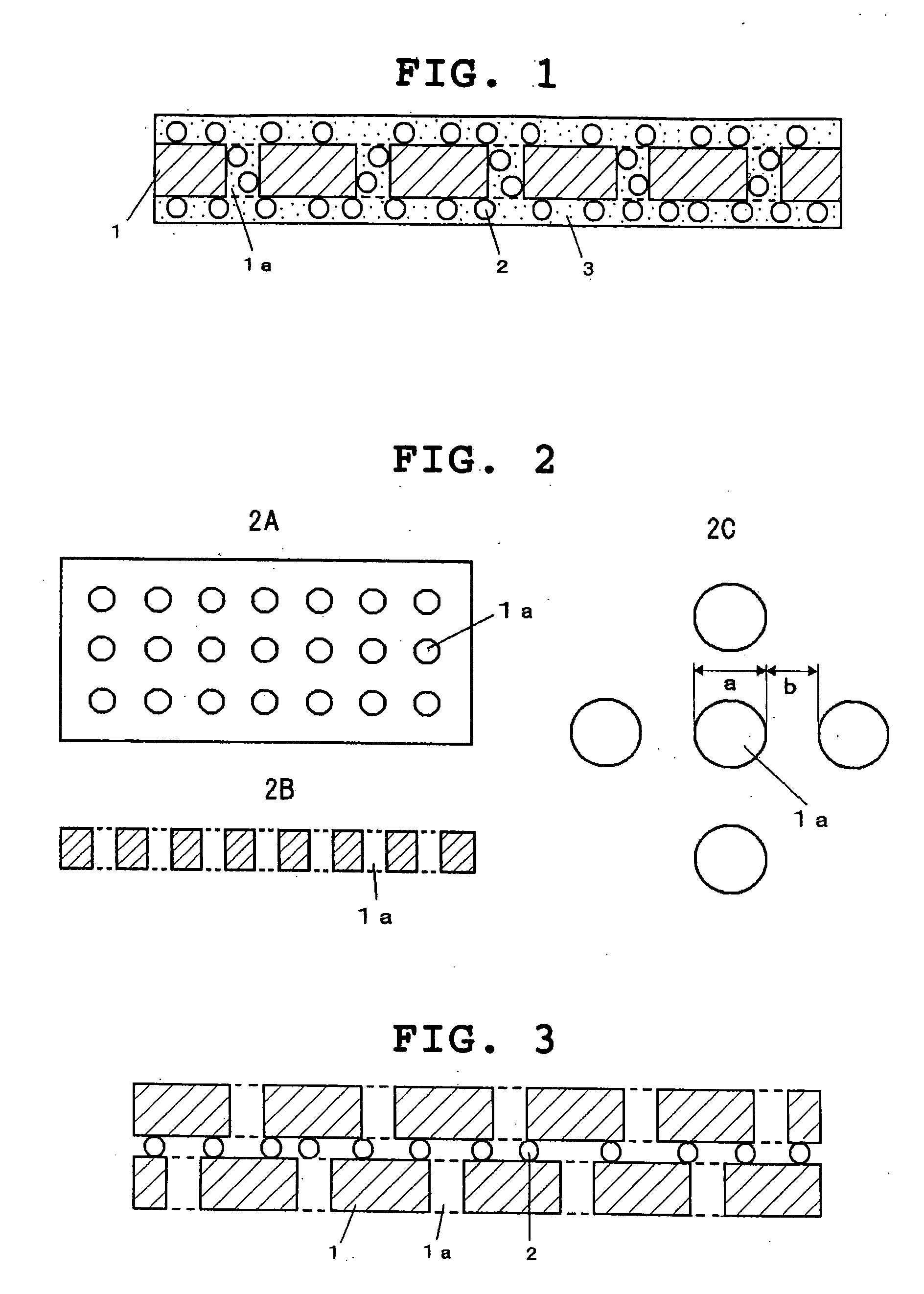
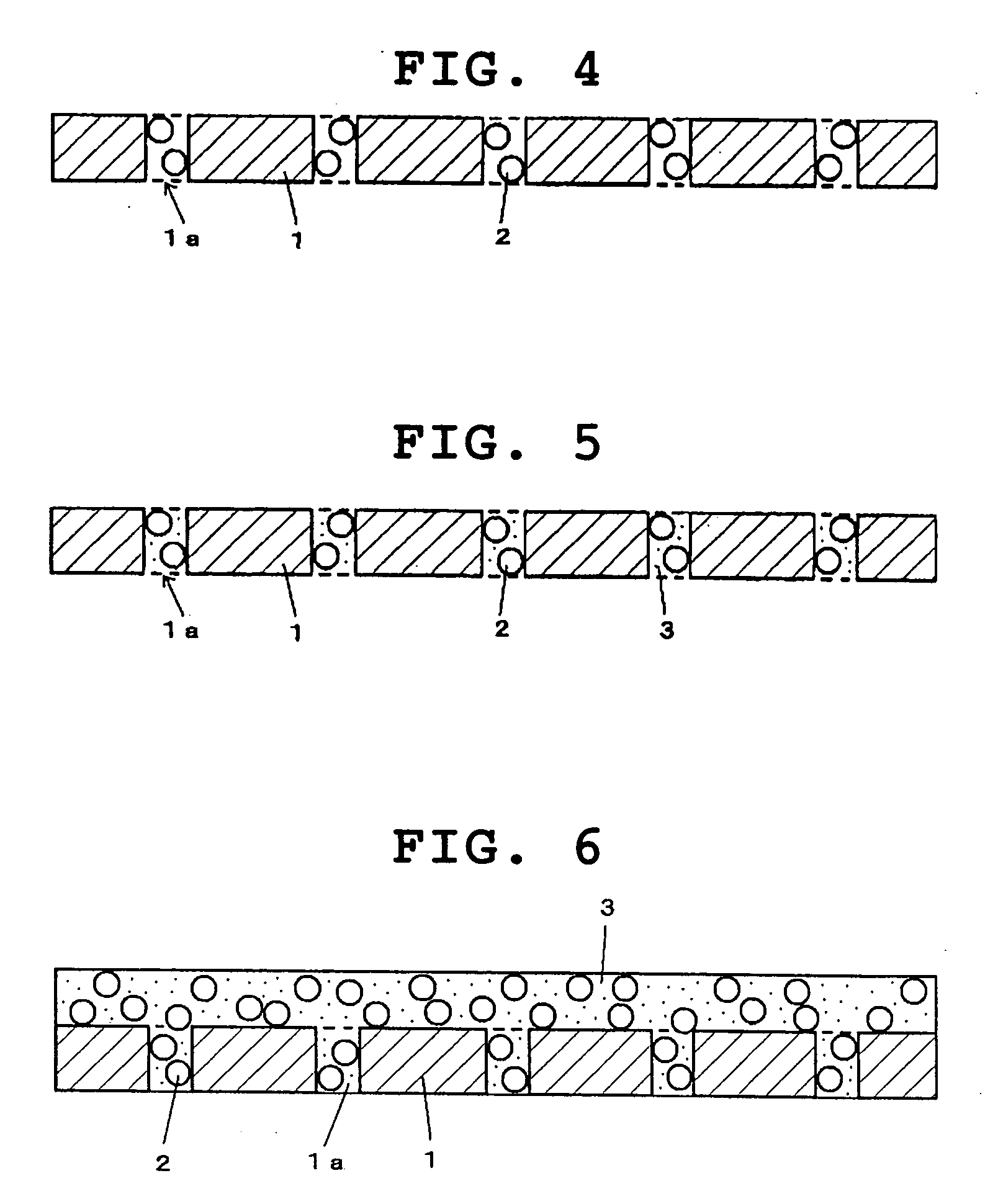
[0071] Vinylidene fluoride homopolymer with an average molecular weight of 300,000 was dissolved in 1-methyl-2-pyrrolidone, to which dibutyl phthalate was added to prepare a solution containing vinylidene fluoride homopolymer by 15 percent by weight. The water content of this solution as measured by the Karl Fischer method was 0.6%. Next, a non-woven fabric with a thickness of 10 μm, made of polyethylene terephthalate fibers made only of fibers with a melting point of 260° C. and on which 5 g / m2 of PTFE grains with a primary average grain size of 0.25 μm and melting point of 320° C. were retained, was placed on the surface of a resin film made of polyethylene terephthalate, and then the aforementioned solution was applied on the non-woven fabric using the casting method. Next, the solvents in the solution that has penetrated into the non-woven fabric were evaporated by way of heating to produce a separator with a thickness of 22 μm, having a porous resin structure of vinylidene fluo...

example 2

[0073] An electronic component separator was produced in the same manner as in Example 1, except that a non-woven fabric with a thickness of 15 μm, made only of vinylon fibers having a melting point of 205° C., was used as the porous base. When the obtained electronic component separator was observed by an electron microscope, no defects such as pinholes were found. The porous resin structure had a series of many pores linked together to connect one side of the porous base to the other side, and the diameters of individual pores were smaller than the thickness of the porous base. The distribution of pore diameters was consistent in the thickness direction of the separator, confirming a uniformity of the porous structure in the thickness direction. The pore diameter of the separator as measured by the bubble point method was 1.0 μm.

example 3

[0074] An electronic component separator was produced in the same manner as in Example 1, except that a microporous resin film with a thickness of 15 μm, made of polyethylene terephthalate with a melting point of 200° C. and having only through pores that are formed in the vertical direction in a manner virtually free from any shielding structure and connecting one side of the resin film to the other side, was used as the porous base. When the obtained electronic component separator was observed by an electron microscope, no defects such as pinholes were found. The porous resin structure had a series of many pores linked together to connect one side of the porous base to the other side, and the diameters of individual pores were smaller than the thickness of the microporous resin film. The distribution of pore diameters was consistent in the thickness direction of the separator, confirming a uniformity of the porous structure in the thickness direction. The pore diameter of the sepa...


PUM

PropertyMeasurementUnit
melting pointaaaaaaaaaa
diameteraaaaaaaaaa

Abstract

The present invention provides a separator that, when used in a lithium ion secondary battery, polymer lithium secondary battery, aluminum electrolytic capacitor or electric double-layer capacitor, offers desired levels of various practical characteristics, undergoes minimal heat shrinkage even when overheated, and exhibits high reliability and excellent workability. The electronic component separator proposed by the present invention comprises a porous base made of a substance having a melting point of 180° C. or above, and a resin structure provided on at least one side of and/or inside the porous base, and the porous base and/or resin structure contains filler grains.

Description

BACKGROUND OF THE INVENTION [0001] 1. Field of the Invention [0002] This invention relates to an electronic component separator that can be used favorably in electronic components, such as lithium ion secondary batteries, polymer lithium secondary batteries, lithium metal batteries, aluminum electrolytic capacitors and electric double-layer capacitors, or more favorably in large lithium batteries and electric double-layer capacitors requiring higher heat resistance, as well as a method for producing the same. [0003] 2. Description of the Background Art [0004] In recent years, demands for such electronic components as lithium ion secondary batteries, polymer lithium secondary batteries, aluminum electrolytic capacitors and electric double-layer capacitors are growing significantly in both industrial and commercial applications, partly due to the rising demands for electrical / electronic equipment, and partly due to the development of hybrid vehicles. Electrical / electronic equipment ar...

Claims


Application Information

Patent Timeline
Patent Type & Authority Applications(United States)
IPC IPC(8): H01G9/02H01M50/414H01M50/417H01M50/426H01M50/449H01M50/457H01M50/489H01M50/491H01M50/497
CPCH01M2/162H01M2/1653H01M2/1686H01M2/1666H01M2/166H01G11/52Y02E60/13Y02E60/10H01M50/449H01M50/44H01M50/446H01M50/417H01M50/457H01M50/414H01M50/491H01M50/489H01M50/426H01M50/497H01M50/42H01M50/423H01M50/4295H01M50/437H01M50/434H01M50/463H01M50/443H01M10/0525H01M10/0565H01G9/02
Inventor TOTSUKA, HIROKISUGIYAMA, MASAHIDETAKAHATA, MASANORI
Owner TOMOEGAWA PAPER CO LTD
Why Eureka
Try Eureka