Thin plate glass laminate and process for producing display device using thin plate glass laminate

Active Publication Date: 2008-06-12
ASAHI GLASS CO LTD
View PDF5 Cites 121 Cited by
  • Summary
  • Abstract
  • Description
  • Claims
  • Application Information

AI Technical Summary

Benefits of technology

[0033]The thin plate glass laminate of the present invention has such advantages that since a thin plate glass substrate and a support glass substrate are laminated by means of a flexible silicone resin layer, bubbles are less likely to be included at the time of lamination, and even if bubbles are included, the bubbles can easily be removed by pressure bonding by means of rolls or pressing. Particularly when lamination of the thin plate glass substrate and the support glass substrate is carried out by a vacuum lamination method or a vacuum pressing method, inclusion of bubbles is suppressed, and adhesion properties are favorable. Further, when lamination of the thin plate glass substrate and the support glass substrate is carried out by a vacuum lamination method or a vacuum pressing method, even if very small bubbles remain, the bubbles will not grow by heating, whereby convex defects are less likely to occur in the thin plate glass substrate.
[0034]Further, it also has such an advantage that even when foreign matters such as dust are included in the interface of the laminate, the flexible silicone resin layer will deform, whereby convex defects are less likely to occur in the thin plate glass laminate.
[0035]Further, since the layer interposed between the thin plate glass substrate and the support glass substrate is a silicone resin layer excellent in heat resistance, the laminate is excellent in heat resistance.
[0036]In the thin plate glass laminate of the present invention, since the thin plate glass substrate and the support glass substrat

Problems solved by technology

To accomplish the above objects, it has been studied to make a glass substrate to be used for display devices thinner, but if the glass substrate is made thin, a decrease in strength becomes problematic, and the amount of deformation tends to be significant, and accordingly such is not applicable to the existing production line.
These methods have latent problems which may adversely affect a display device to be produced.
That is, by the method of fixing the glass substrates by means of electrostatic adsorptivity or vacuum adsorptivity, the method of fixing both ends of the glass substrates by means of glass frit, or the method of fusing the two glass substrates by irradiating a portion in the vicinity of edge surfaces of peripheral portions with laser bea

Method used


Image

  • Thin plate glass laminate and process for producing display device using thin plate glass laminate
  • Thin plate glass laminate and process for producing display device using thin plate glass laminate
  • Thin plate glass laminate and process for producing display device using thin plate glass laminate

Examples


example 1

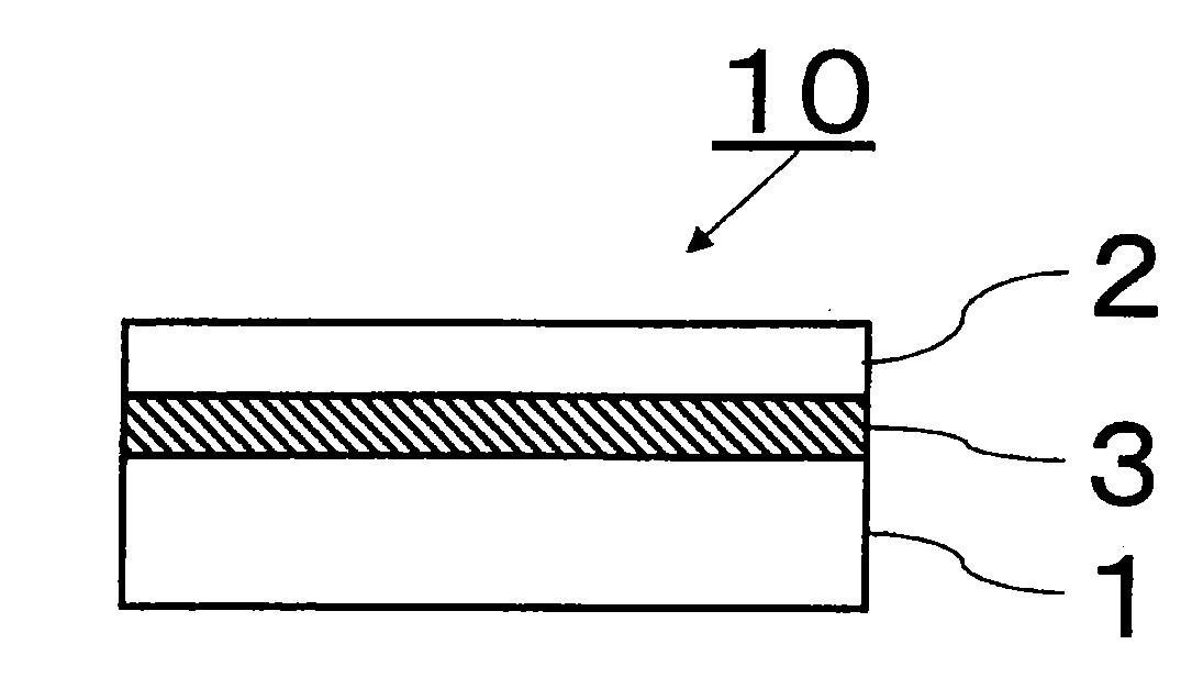
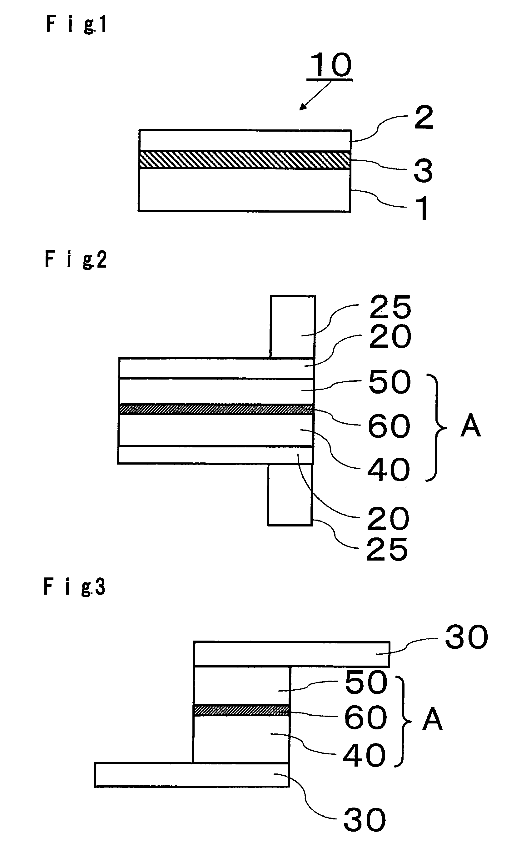
[0111]A support glass substrate of 400 mm×300 mm×0.7 mm in thickness having a coefficient of linear expansion of 38×10−7 / ° C. (AN100, manufactured by Asahi Glass Company, Limited) was washed with pure water and cleaned by e.g. UV cleaning, and then a mixture comprising 100 parts by mass of a solventless addition reaction silicone for release paper (KNS-320A, manufactured by Shin-etsu Silicones) and 2 parts by mass of a platinum catalyst (CAT-PL-56, manufactured by Shin-etsu Silicones) was applied (application amount: 10 g / m2) to the support glass substrate by a spin coater and heat-cured at 180° C. for 30 minutes in the air to obtain a silicone resin layer having a thickness of 16 um.

[0112]The surface on the side to be in contact with a silicone resin layer of a thin plate glass substrate (AN100) of 400 mm×300 mm×0.1 mm in thickness having a coefficient of linear expansion of 38×10−7 / ° C. was washed with pure water and cleaned by e.g. UV cleaning, and then the silicone resin layer-f...

example 2

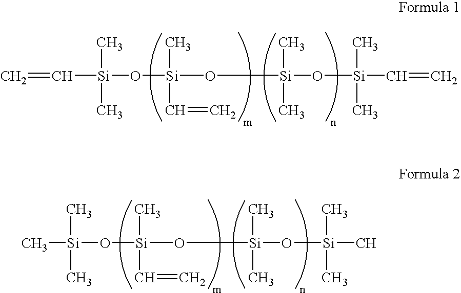
[0125]A thin plate glass laminate (thin plate glass laminate B) of the present invention was obtained in the same manner as in Example 1 except that instead of the mixture comprising 100 parts by mass of a solventless addition reaction silicone for release paper (KNS-320A, manufactured by Shin-etsu Silicones) and 2 parts by mass of a platinum catalyst (CAT-PL-56, manufactured by Shin-etsu Silicones), a mixture comprising a linear polyorganosiloxane having vinyl groups at both ends (“8500”, manufactured by Arakawa Chemical Industries, Ltd.), a methyl hydrogen polysiloxane having hydrosilyl groups in its molecule (“12031”, manufactured by Arakawa Chemical Industries, Ltd.) and a platinum catalyst (“CAT12070”, manufactured by Arakawa Chemical Industries, Ltd.) was used. The mixing ratio of the linear polyorganosiloxane and the methyl hydrogen polysiloxane was adjusted so that the molar ratio of the hydrosilyl groups to the vinyl groups became 1.5 / 1. The platinum catalyst was added in a...

example 3

[0134]A thin plate glass laminate (thin plate glass laminate C) was obtained in the same manner as in Example 2 except that the mixing ratio of the linear polyorganosiloxane and the methyl hydrogen polysiloxane was adjusted so that the molar ratio of the hydrosilyl groups to the vinyl groups became 1.0 / 1.

[0135]In the thin plate glass laminate C, the thin plate glass substrate was closely bonded to the silicone resin layer without formation of bubbles, was free from convex defects and had favorable smoothness.

[0136]The formed thin plate glass laminate C was evaluated as follows.

(1) Simplified Peel Test

[0137]The thin plate glass laminate C was disposed so that the thin plate glass substrate faced upward, and the support glass substrate was fixed by means of a jig. In such a state, a part of the peripheral portion of the thin plate glass substrate was peeled from the support glass substrate with a razor, and further, the thin plate glass substrate was manually separated from the suppor...


PUM

PropertyMeasurementUnit
Temperatureaaaaaaaaaa
Percent by massaaaaaaaaaa
Thicknessaaaaaaaaaa

Abstract

To provide a thin plate glass laminate of a thin plate glass substrate and a support glass substrate, which suppresses inclusion of bubbles and occurrence of convex defects due to foreign matters, from which the thin plate glass substrate and the support glass substrate are easily separated, and which is excellent in heat resistance, a process for producing a display device using such a thin plate glass laminate, and a silicone for release paper for such a thin plate glass laminate.
A thin plate glass laminate formed by laminating a thin plate glass substrate and a support glass substrate, wherein the thin plate glass substrate and the support glass substrate are laminated by means of a silicone resin layer having releasability and non-adhesive properties.

Description

TECHNICAL FIELD[0001]The present invention relates to a laminate of a glass substrate to be used for a display device such as a liquid crystal display or an organic EL display, more specifically, a thin plate glass substrate to be used for production of a display device using the thin plate glass substrate, with a support glass substrate, and a process for producing a display device using it, and a silicone for release paper for such a thin plate glass laminate.BACKGROUND ART[0002]In the field of liquid crystal display devices (LCD), organic EL display devices (OLED), particularly portable display devices such as mobile or portable phones, weight saving and reduction in thickness of display devices have been important objects.[0003]To accomplish the above objects, it has been studied to make a glass substrate to be used for display devices thinner, but if the glass substrate is made thin, a decrease in strength becomes problematic, and the amount of deformation tends to be significa...

Claims


Application Information

Patent Timeline
IPC IPC(8): B29C63/00
CPCB32B7/06B32B17/06B32B17/10036B32B25/20G02F1/1333Y10T156/1972H01L51/0096B32B17/10798Y10T156/1189Y10T428/1068G02F2001/133302Y10T428/31663C09K2323/053G02F1/133302H10K77/10B32B17/10G09F9/00B32B27/283B32B2307/306B32B2307/748B32B2319/00
Inventor HIGUCHI, TOSHIHIKO
Owner ASAHI GLASS CO LTD
Why Eureka
Try Eureka