[0005] The foregoing problems are solved and a technical advance is achieved in an illustrative
valve prosthesis, such as an artificial
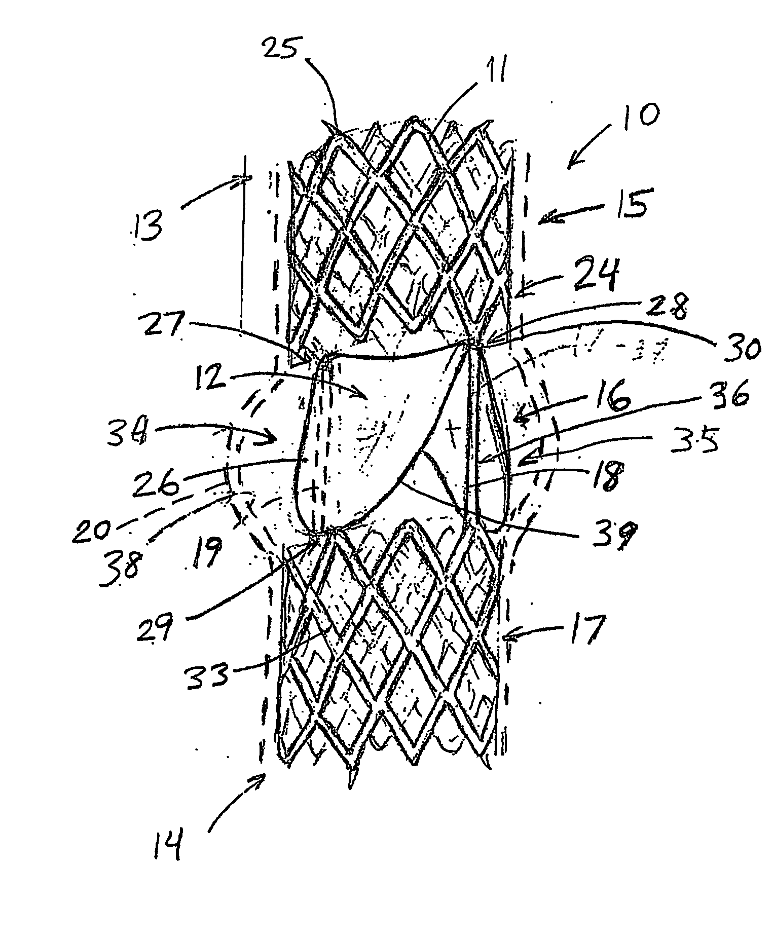
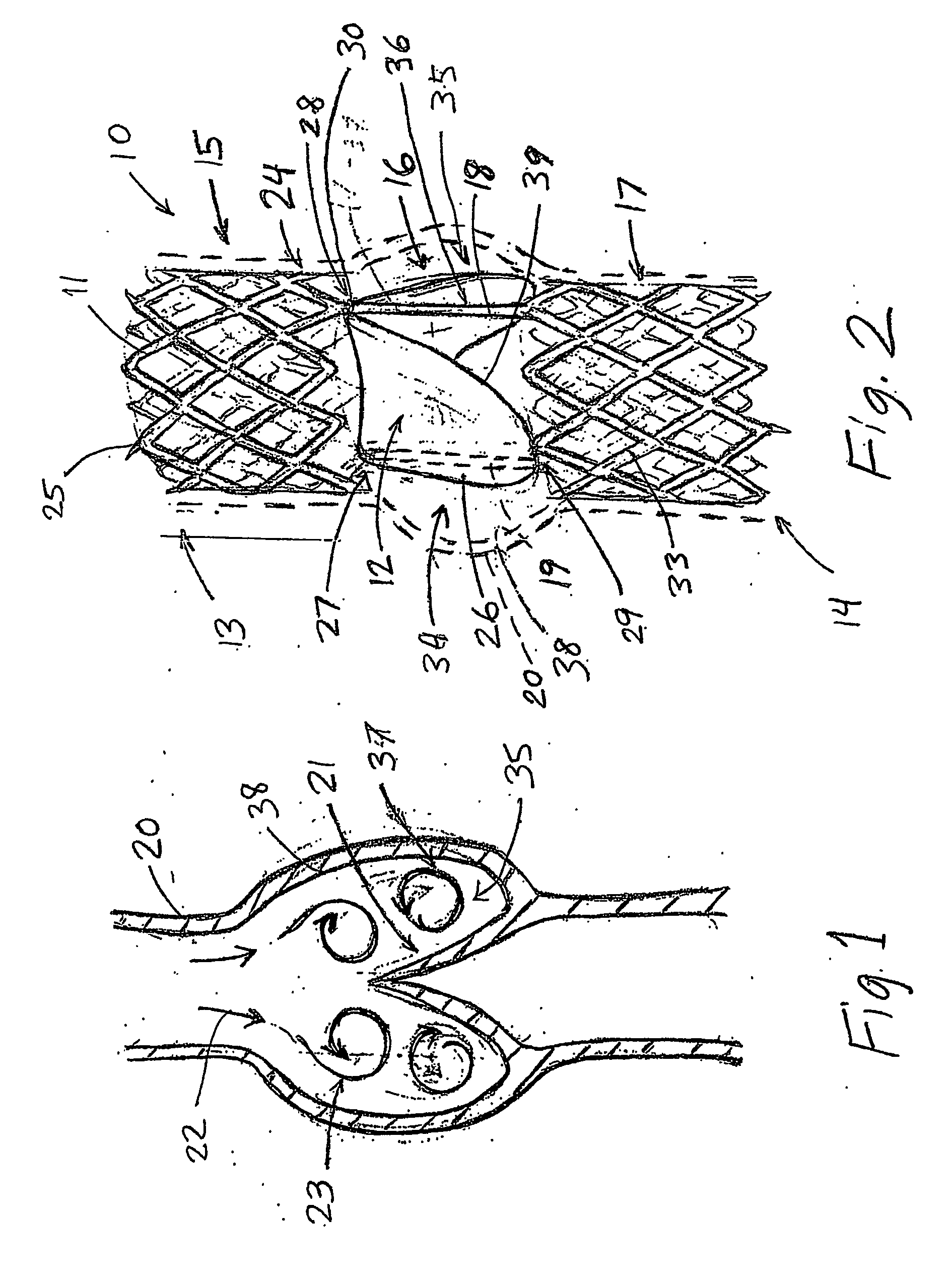
venous valve, having a valve structure and a self-expanding or otherwise expandable support structure that upon deployment within the
vein, helps create an artificial sinus or larger pocket in the vessel surrounding the valve structure of sufficient size and shape to stimulate flow patterns or vortices which facilitate clearing of the blood or other bodily fluid that would otherwise
pool therein. The structural adaptations result in more turbulent flow, increased velocity of flow, larger and / or more numerous vortices, other factors, or a combination of the above that prevent stagnant, hypoxic areas from occurring around the valve structure. Furthermore, the modified flow may also contribute to helping close the leaflets to form a seal and prevent leakage of fluid back through the valve. The artificial sinus or enlarged pockets simulate the function of the natural sinus that exists at the site of most natural valves in the deep veins of the lower legs and which may explain why the problem of
thrombus forming around the valve structure has been observed to be a common problem in prosthetic venous valve designs lacking such a sinus area.
[0010] In still yet another aspect of the present invention, the support structure of the
prosthesis is configured such that the attachment pathway (defined herein as the interface between the lateral, outer edges of the leaflets and the struts and / or vessel walls to which they are attached to establish and define the shape and configuration of the plurality of leaflets comprising the valve structure as deployed) has a first, proximal portion in which the one or more longitudinal attachment struts extending from the proximal bends or commissures that carry and support the proximal outer edges of the leaflets (and span the orifice) have a strongly longitudinal orientation with respect to the longitudinal axis of the
prosthesis and valve structure, and a
distal portion of the attachment pathway that extends circumferentially (laterally) and distally from the longitudinal axis to form the bottom or distal edge of the outer leaflet edge or perimeter. When viewed from the side, the support frame and attached leaflet is configured such that the angle (angle α) formed between the opposing leaflets, as carried along the proximal attachment pathway, is substantially less than the angle (angle β) formed between distal attachment pathways and the vessel walls. This configuration results in leaflets having large coaptable area relative to the overall surface area, which improves sealing (including reducing the effects of retraction by the valve material) and allows for larger pockets surrounding the leaflets which, like the sinus, facilitate the creation of larger, stronger vortices of
retrograde flow that help close the leaflets and clear away blood or fluid that could otherwise stagnate under conditions where the surrounding pockets are smaller in size. As used herein, the term ‘retrograde flow’ is defined as bodily fluid traveling in a distal direction (toward the feet), whether due to gravitational forces, redirection due to contact with the
prosthesis or bodily lumen walls, or by some other means.
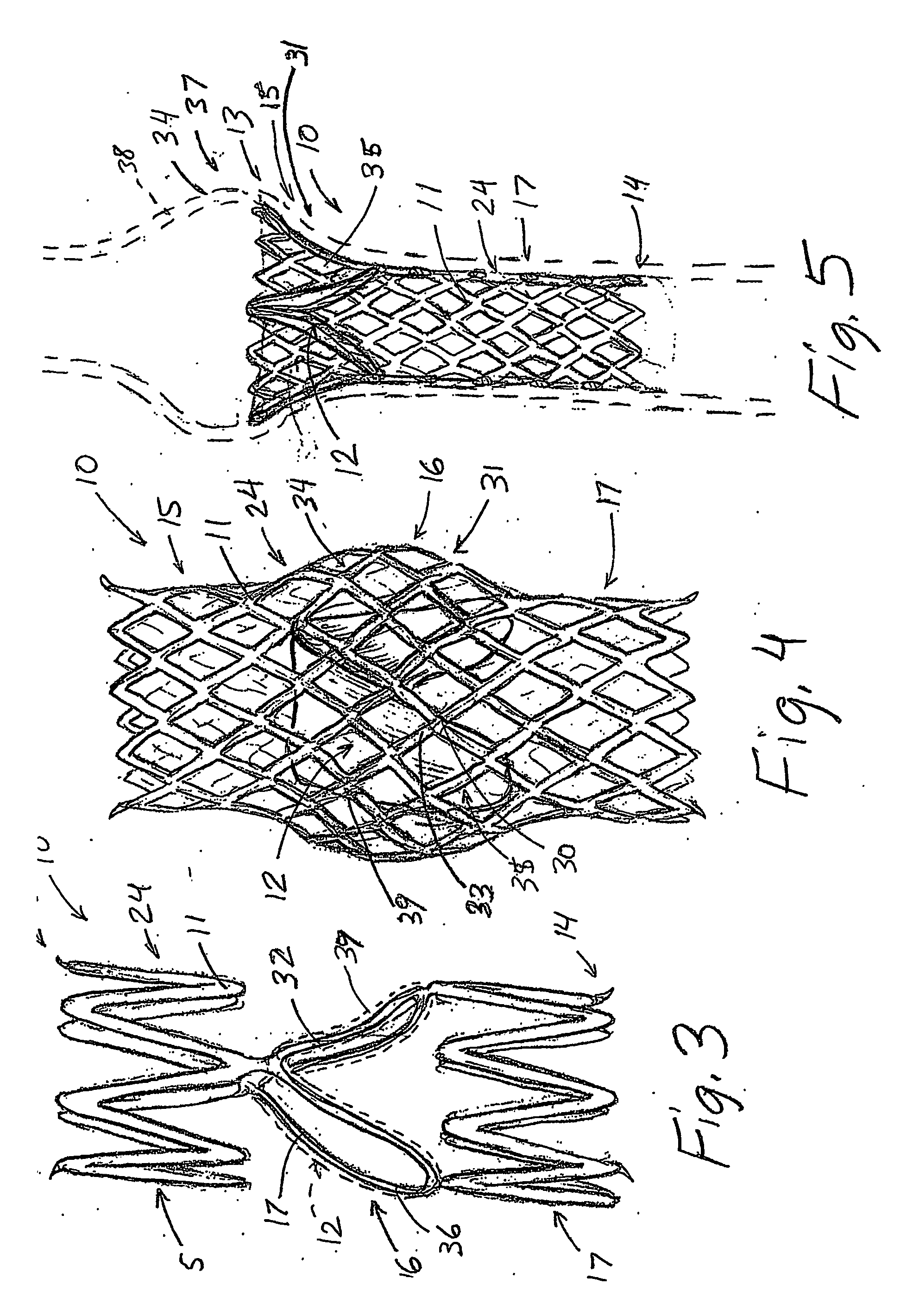
[0011] A first embodiment of this aspect of the invention includes a frame comprising a pair of longitudinal attachment struts originating from each
commissure bend. The struts extend in generally longitudinal direction, diverging relatively or not at all toward the distal end of the prosthesis before more acutely diverging as they curve laterally and circumferentially away from the proximal strut portions such that the transition between the proximal and distal portions of attachment pathway comprises a bend having a
radius that is distinctly smaller than that of the adjacent strut portions (the proximal portions being straight some embodiments). The distal attachment pathways converge to define the bottom outer edge of each leaflet. In a second embodiment of this aspect of the invention, the support frame of the prosthesis includes a pair of substantially parallel longitudinal attachment struts to which the leaflets are attached to form the proximal portion of the attachment pathway, and distal attachment struts extending circumferentially and laterally outward from the substantially parallel struts to form the
distal portion of the attachment pathway. The support frame carrying the valve structure may be advantageously comprised of radial sections (e.g., quadrants in a
bicuspid valve) that are of an identical pattern but with alternating orientation such as to provide for radial stability and better expandability characteristics. The radial section not carrying the leaflet proximal outer edges serves as lateral support structure for adding longitudinal stability and help protecting the leaflets from adhering to the vessel walls. The parallel struts provide for advantageous bending and torsional characteristics such that the frame has utility as a
stent. In an alternate embodiment of the support structure, the lateral outer edges of the opposing leaflets can be attached to single longitudinal attachment strut having a pair of distal struts extending laterally outward and circumferentially to carry the bottom half of the leaflet and define the overall shape thereof. The strut may be thicker than adjacent struts and include aperture therealong for facilitating attachment of the valve structure.
[0012] In still yet another aspect of the present invention, the proximal section of the valve is wider in
diameter at its proximal end, which anchors the prosthesis in the vessel, and narrower at the interface between the proximal and intermediate sections. This, in combination with a leaflet structure that maximizes pocket size, results in retrograde flow being subject to a
Venturi effect which increases flow and the strength of the vortices to close the valve and clear the pockets of potentially stagnating fluids.

