Release latch for pre-terminated cassette

a pre-terminated cassette and latch technology, applied in the field of pre-terminated cassettes, can solve the problems of difficult to disengage the latch and remove the pre-terminated cassette, and the difficulty of the cassette to be removed,

Active Publication Date: 2010-03-30
PANDUIT
View PDF73 Cites 206 Cited by
  • Summary
  • Abstract
  • Description
  • Claims
  • Application Information

AI Technical Summary

Benefits of technology

[0054]An advantage of this embodiment of the invention is that the pre-terminated cassette 115 requires very little compression to release the latch and disengage the cassette during intentional removal of the cassette from the patch panel. The cantilever beam may be easily deflected upon pressure being applied. Further, as with pre-terminated cassette 80 having latch 84 described above, the release latch 122 for the pre-terminated cassette 115 enables the customer to quickly remove a pre-terminated cassette from a patch panel without any tools and with the use of only one hand for any desired moves, additions, or changes.

Problems solved by technology

Once these cassettes are installed in patch panels, it is often difficult to remove the cassette because the latch is not easily accessible.
When a plurality of cassettes are installed in the patch panels in a data center, it is difficult to disengage the latch and remove the pre-terminated cassette because the customer is required to reach between rows of cables to disengage the latch.

Method used


Image

  • Release latch for pre-terminated cassette
  • Release latch for pre-terminated cassette
  • Release latch for pre-terminated cassette

Examples


Embodiment Construction

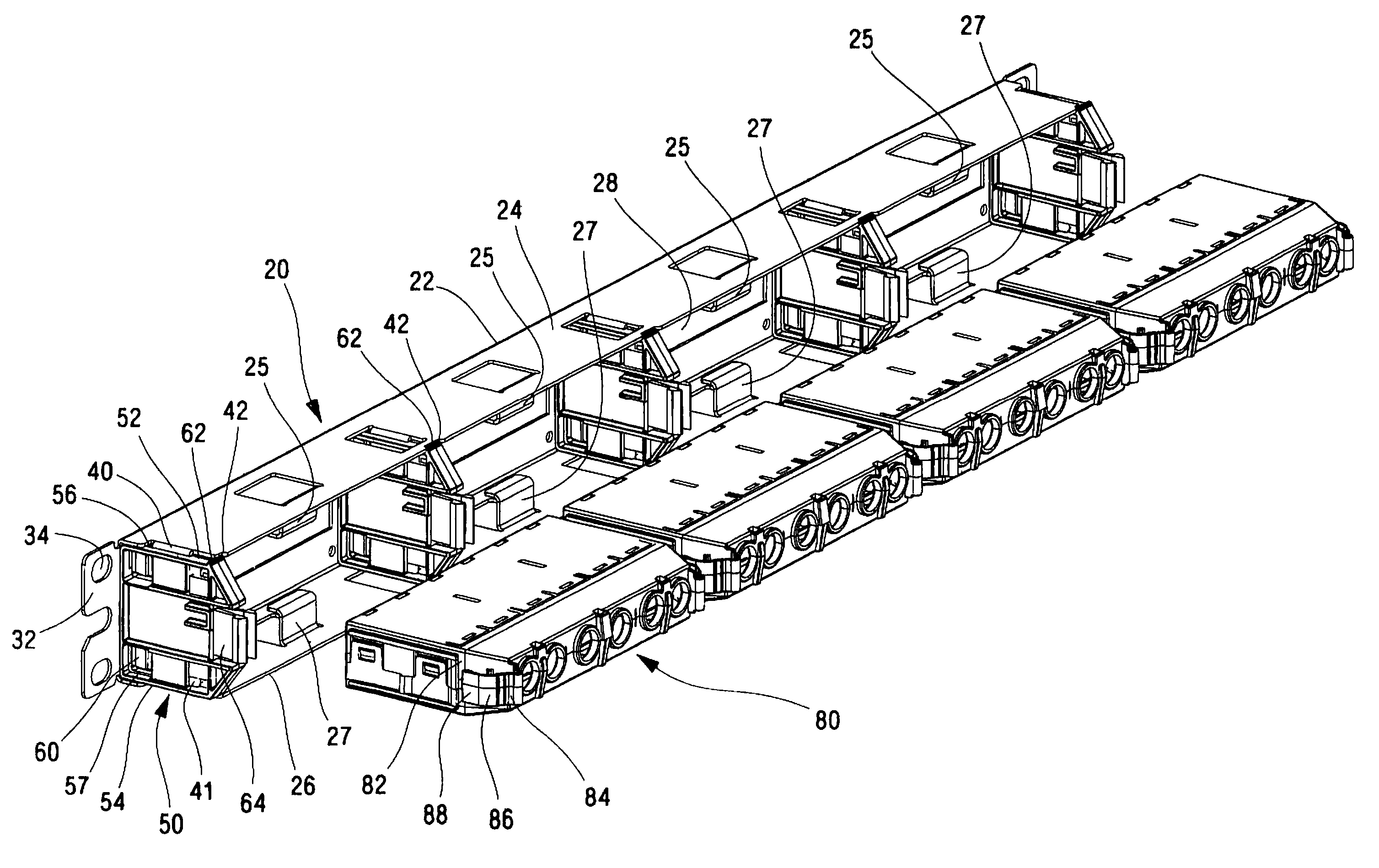
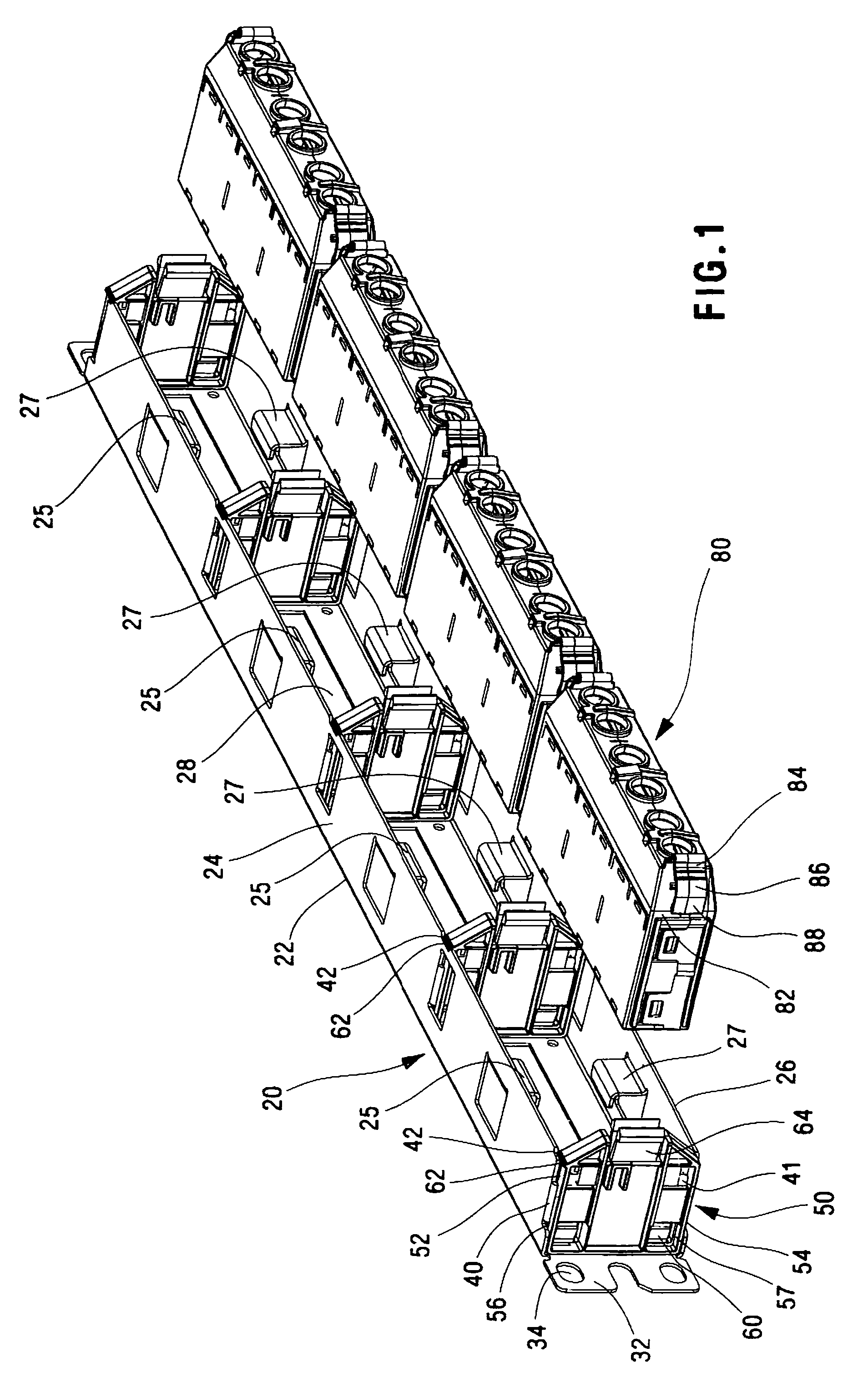
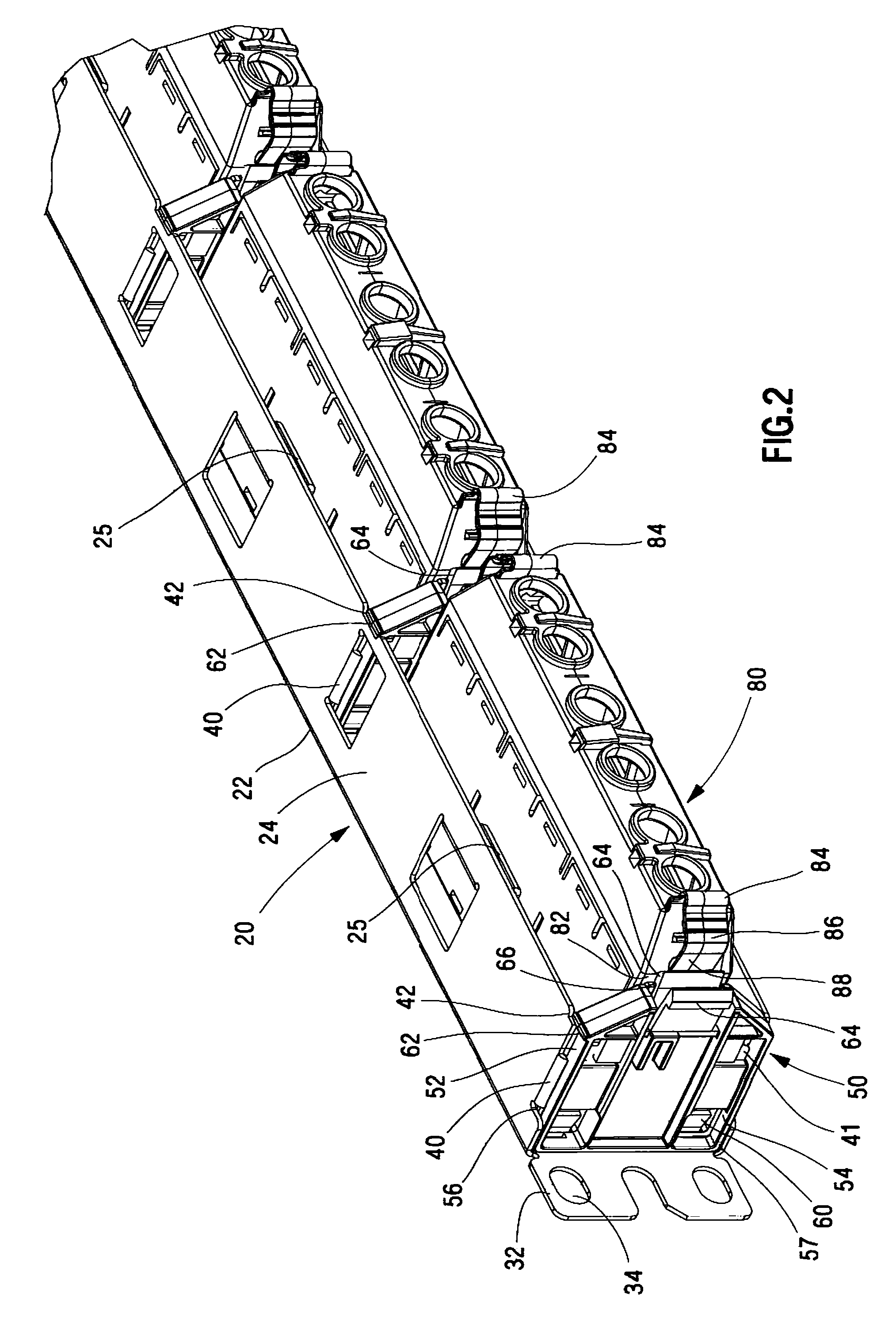
[0031]FIGS. 1 and 2 illustrate a typical patch panel 20 with a plurality of side guides 50 installed in the patch panel. The patch panel 20 receives a number of pre-terminated cassettes 80 that are positioned between adjacent side guides 50. The pre-terminated cassettes 80 are inserted straight into the patch panel 20 until the cassettes 80 snap into the patch panel between adjacent side guides 50.

[0032]FIG. 3 illustrates an exploded view of the patch panel 20 with a side guide 50 of the present invention. The patch panel 20 includes a frame 22 with a top flange 24, a bottom flange 26 and a plurality of openings 28. Each end of the patch panel 20 includes a mounting plate 32 with mounting apertures 34 for securing the patch panel to a network rack (not illustrated).

[0033]The patch panel 20 includes a plurality of panel tabs 40, 41. As illustrated in FIG. 3 the panel tabs 40 extend downwardly from the top flange 24 and panel tabs 41 extend upwardly from the bottom flange 26. The pane...


PUM


Abstract

A release latch for a pre-terminated cassette is described. The pre-terminated cassette includes a release latch to allow removal of the pre-terminated cassette from a patch panel, where the patch panel includes a retaining feature for retaining the pre-terminated cassette. The release latch includes a cantilever beam located on the sidewall of the pre-terminated cassette. The cantilever beam has a hinge point that allows the beam to deflect with respect to the sidewall. The release latch further includes a depressing tab provided at the distal end of the cantilever beam and a latch tab protruding from the surface of the cantilever beam between the hinge point and the depressing tab. The latch tab is capable of engagement with the retaining feature of the patch panel when the cassette is installed in the patch panel.

Description

CROSS-REFERENCE TO RELATED APPLICATIONS[0001]The present patent application claims priority under 35 U.S.C. § 119(e) to U.S. Provisional Patent Application Ser. No. 60 / 829,070, which was filed Oct. 11, 2006. the full disclosure of which is incorporated herein by reference. The present patent application also claims priority under 35 U.S.C. § 119(e) to U.S. Provisional Patent Application Ser. No. 60 / 954,863, which was filed Aug. 9, 2007, the full disclosure of which is incorporated herein by reference.FIELD OF THE INVENTION[0002]The present invention relates to a pre-terminated cassette and, more particularly. to a release latch for removing a pre-terminated cassette installed in a patch panel.BACKGROUND OF THE INVENTION[0003]Pre-terminated copper or fiber cable cassettes provide quick and reliable installation of cables to patch panels. The pre-terminated cassettes are assembled according to the customer's specifications prior to shipment. The performance of the cassettes is also ve...

Claims


Application Information

Patent Timeline
Patent Type & Authority Patents(United States)
IPC IPC(8): G02B6/00
CPCH04Q1/13H04Q1/14H04Q1/20
Inventor WAGNER, MATTHEW MWOJCIK, ALAN FDUCHARME, PAUL BMIRUSKY, WILLIAM FFRITZ, ROBERT L
Owner PANDUIT
Why Eureka
Try Eureka