
Labeling device for labeling objects, in particular moving objects

a labeling device and moving object technology, applied in the field of labeling devices, can solve the problems of affecting the effect of labeling, affecting the quality of labeling, so as to achieve the effect of alleviating or eliminating on

Active Publication Date: 2014-02-13
MAREL HF
View PDF4 Cites 56 Cited by
  • Summary
  • Abstract
  • Description
  • Claims
  • Application Information

AI Technical Summary

Benefits of technology

The patent text describes a label carrying mechanism that prevents labels from being blown away from objects and automatically moves back to its starting position for labeling. It uses a negative pressure pad with flexibility to deflect and apply a negative pressure on the objects, ensuring efficient labeling. The movement of the label carrying mechanism can be adjusted to select an exact position of the labels. The technical effects of this mechanism are improved labeling efficiency and precision in label placement.

Problems solved by technology

The disadvantage with such a labelling device is that if the objects to be labelled have uneven surfaces, there is a risk that the labels will not attach to these uneven surfaces, and be blown away from the surfaces.
Moreover, if the height of the objects to be labelled is irregular and some of the objects have a height that is above the above mentioned pre-set height, the objects will be hit by the linearly displaceable piston, causing a blocking of the labelling device.
Accordingly, this blocking does not only requrie extra manpower to monitor the device but also the impact from the piston on the object can easily damage the packing and even the object and delay the labelling operation.

Method used


Image

  • Labeling device for labeling objects, in particular moving objects
  • Labeling device for labeling objects, in particular moving objects
  • Labeling device for labeling objects, in particular moving objects

Examples


Embodiment Construction

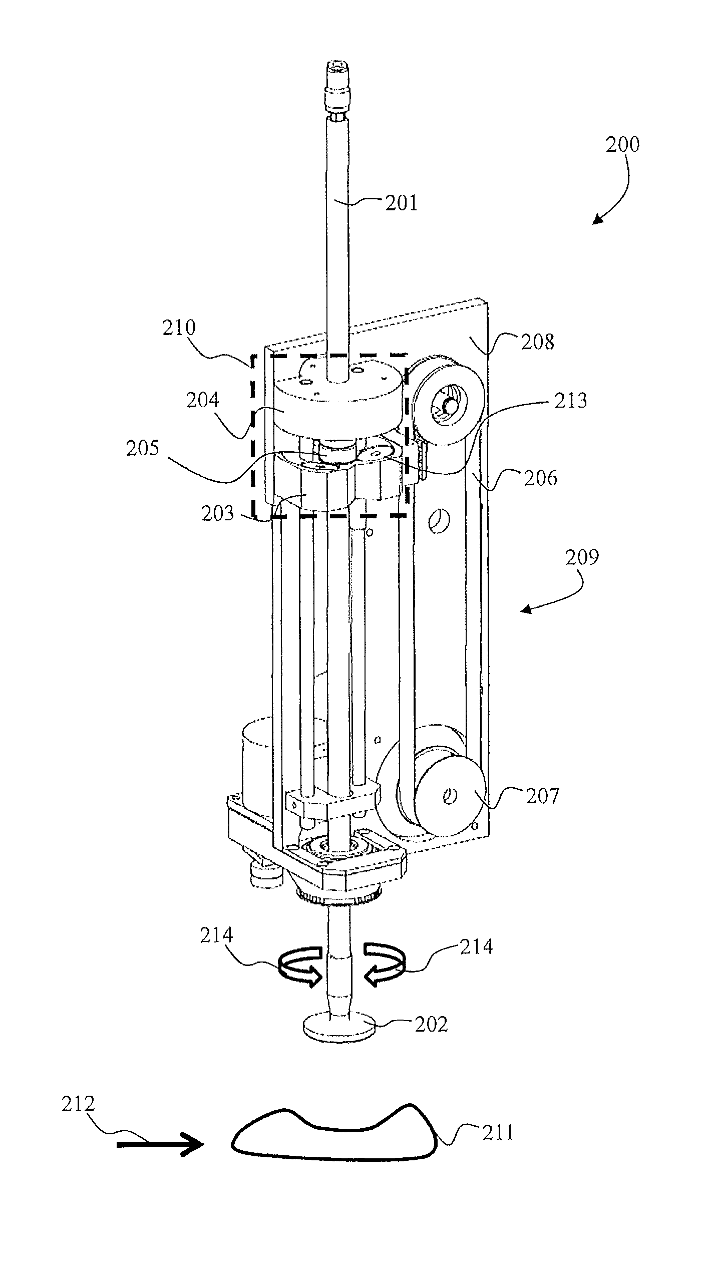
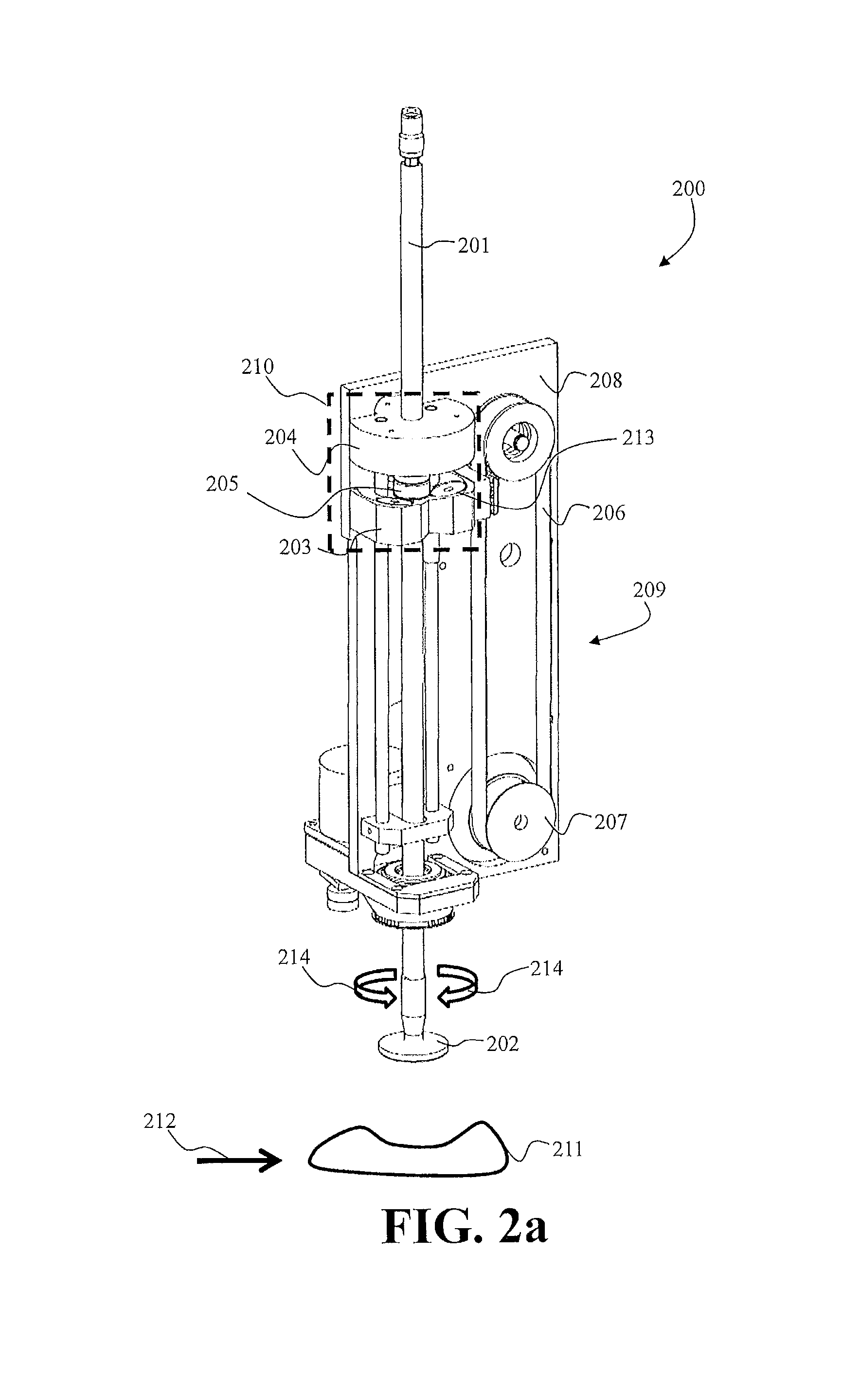
[0034]FIGS. 2 to 4 depict perspective views and front views of one embodiment of a labelling device 200 according to the present invention for labelling objects 211, in particular moving objects as indicated by the arrow 212, where the objects may be moved on any type of conveyor means (not shown). The objects may be of any type, such as food products or any type of non-food product.

[0035]The labelling device comprises a linearly displaceable piston 201, a label carrying mechanism 202, a force-switching-state system 210, a moving mechanism 209 and a frame structure 208.

[0036]The linearly displaceable piston 201 is operably connectable to the moving mechanism 206 for moving the piston from a resting position to a labelling position and vice versa. In this embodiment, the moving mechanism comprises an endless belt 206 extending alongside the piston 201 between two wheels including a driving wheel 207. The coupling between the piston 201 and the endless belt 206 will be discussed in mo...


PUM

PropertyMeasurementUnit
threshold height levelaaaaaaaaaa
repelling forceaaaaaaaaaa
forceaaaaaaaaaa

Abstract

A labelling device includes a linearly displaceable piston operably connectable to a moving mechanism for moving the piston from a resting position to a labelling position. A label carrying mechanism is arranged at the distal end of the piston for carrying an adhesive label and affixing the adhesive label to an object via physical contact at the labelling position of the piston. A force-switching-state system is provided to maintain the piston in relation to the moving mechanism in an attracting force state and the piston moves with the moving mechanism. The physical contact creates an opposite repelling force from the object onto the label carrying mechanism causing separation of the displaceable piston from the moving mechanism. This separation causes a change of the force state of the displaceable piston from an attracting to a repelling force state, causing the linearly displaceable piston to move back to the resting position.

Description

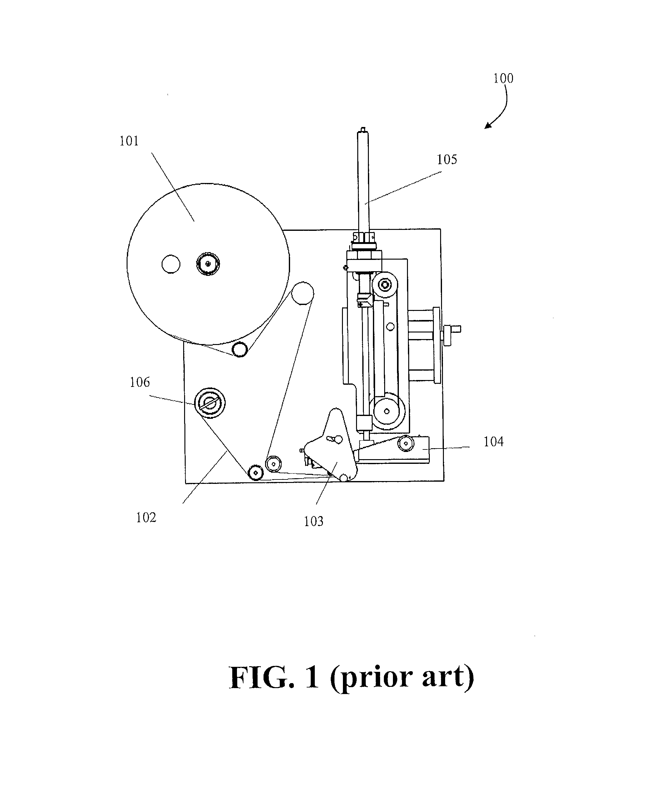
FIELD OF THE INVENTION[0001]The present invention relates to a labelling device adapted to label objects, in particular moving objects such as food objects.BACKGROUND OF THE INVENTION[0002]FIG. 1 depicts a prior art labelling device 100 for labelling moving objects. A label reel is placed in a holder 101 (label reel assembly), from where a web 102 is manually threaded through a printhead mechanism and finally onto the web take up assembly 106. The web is driven through the printhead mechanism 103 which houses a printing device that prints a label as it passes through the mechanism. Once printed the label is stripped off its backing web or carrier and fed onto a label pickup assembly 104. A linearly displaceable piston 105 is extended to take the label from the label pickup assembly, where the label may be rotated and finally held at a pre-set height above the item being labelled. Once the item is in position the label is blown onto the item.[0003]The disadvantage with such a labelli...

Claims


Application Information

Patent Timeline
Patent Type & Authority Applications(United States)
IPC IPC(8): B65C9/08
CPCB65C9/08B65C9/36B65C1/021Y10T156/17Y10T156/1705Y10T156/1744
Inventor BATES, STEVEN
Owner MAREL HF
Learn More