Method of providing proper vertebral spacing

a technology of proper vertebral spacing and bone implants, applied in the field of implantable bone implants or prostheses, can solve the problems of not enabling the use of rigid cages from a posterior, small inside volume, and complicating implementation, and achieve the effects of improving consolidation, facilitating use, and facilitating placemen

Inactive Publication Date: 2002-04-16
OSTEOIMPLANT TECH
View PDF121 Cites 566 Cited by
  • Summary
  • Abstract
  • Description
  • Claims
  • Application Information

AI Technical Summary

Benefits of technology

To provide better anchoring in the bone and to avoid any subsequent migration of the cage, the outside surfaces of said branches are preferably either knurled, grooved, or threaded using a thread profile having projecting ridges, etc.
Also, to reduce any risk of rotation after implantation, and thus reduce any risk of displacement of the cage, while simultaneously increasing contact area with the faces of the vertebrae, at least the seat of the implant and preferably also the sides of the branches have at least two optionally parallel flats, each disposed symmetrically about the axis of the implants between two successive branches. These flats, optionally assisted by the generally ovoid shape of the cage, make better retention possible after expansion by reducing any risk of the implant rotating. In addition, said ovoid shape can make it possible, better than if the outer generator line of the basic cylindrical shape of the cage at rest were a straight line, to return after expansion to an outside profile that is conical and without curvature, thereby providing better-distributed thrust against the body of the vertebrae, thus helping the bone graft to take better.
To stiffen the cage at its posterior end, particularly if there is a large orifice in the seat, thereby making it easier to fill the cage with bone matter after the cage has been put into place and expanded, the orifice of said seat is suitable for receiving a plug for closing the inside volume of the cage. By way of example, the plug can be screwed into said orifice, in which case the orifice is also threaded. Under such circumstances, the plug prevents bone matter from escaping and depending on the material out of which it is made, it can also stiffen the cage.
The presence of at least four branches, and possibly four to eight branches, makes it possible to obtain bilateral expansion, and thereby better jamming against the two facing faces of the vertebrae, and the absence of a link part or rod between the spacer maintaining said expansion and the orifice or plug in the end seat guarantees a larger inside volume for receiving a large quantity of bone matter, thereby improving consolidation and joining by fusion, in particular between the vertebrae that are to be held together. Said filling operation is made that much easier by having a large orifice at the posterior end of the cage through said seat.
In addition, said orifice makes it possible to scrape the faces of the vertebrae through the slots situated between the branches in the bottom and top faces of the cage.
The present invention thus provides numerous advantages over existing implants or cages, of the kind already mentioned, and other advantages can also be provided but those given above suffice to demonstrate the novelty and the usefulness of the invention.

Problems solved by technology

In addition, the inclinations of the facing vertebral faces to which a given angular position is to be imparted do not enable rigid cages to be used from a posterior direction: they can be inserted only from an anterior direction.
Nevertheless, such devices which are more mechanical than hollow and rigid cages, and therefore more complex, leave a smaller inside volume for the fusion graft, and because of their flat shape which is not circularly symmetrical, even though they are better at ensuring a given bearing angle between the vertebrae, they require a passage of the same rectangular section to be prepared to receive them, and that complicates implementation.

Method used


Image

  • Method of providing proper vertebral spacing
  • Method of providing proper vertebral spacing
  • Method of providing proper vertebral spacing

Examples


Embodiment Construction

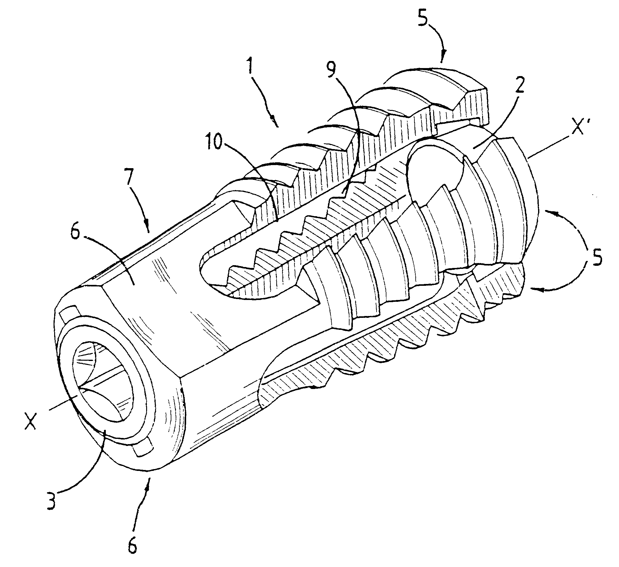
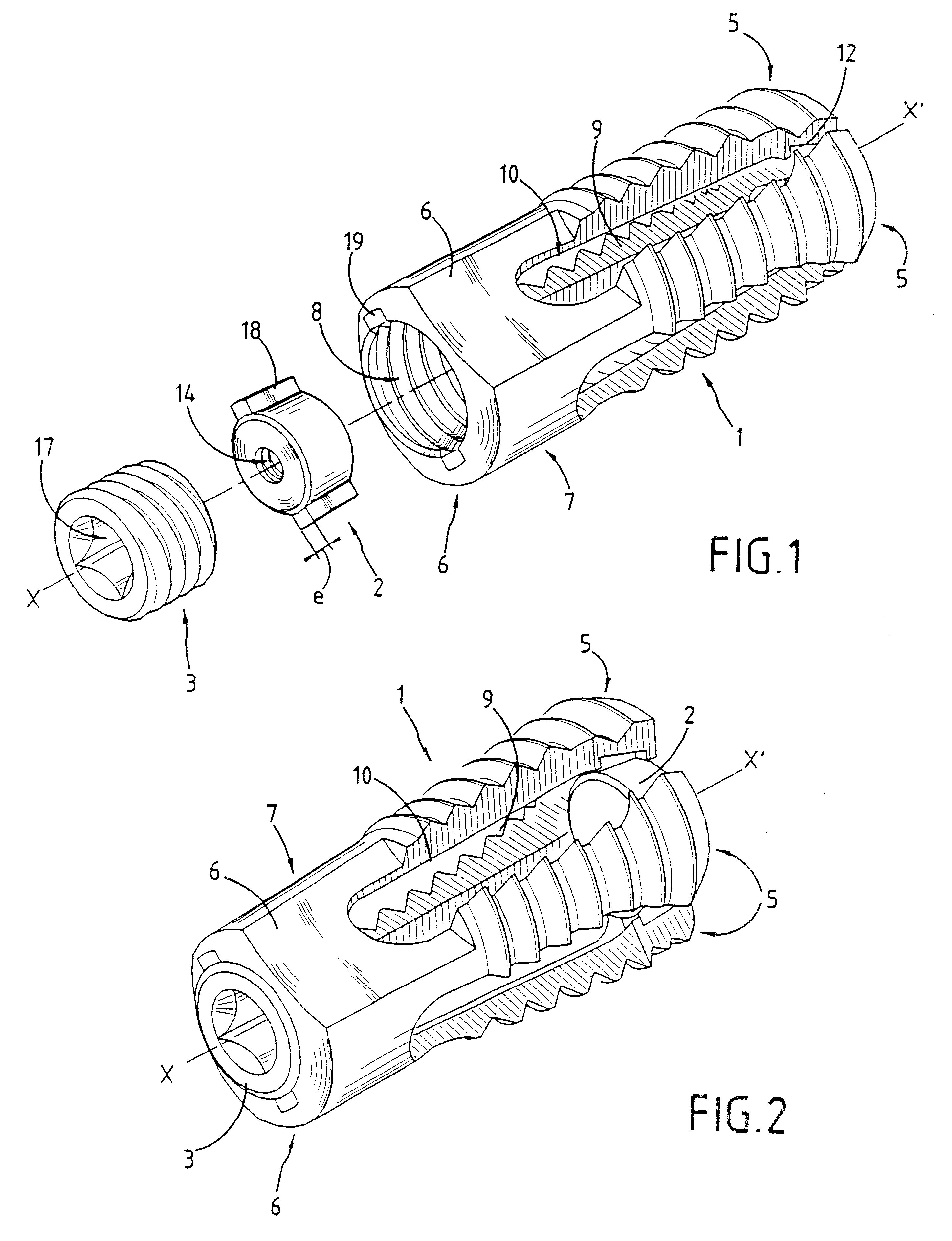
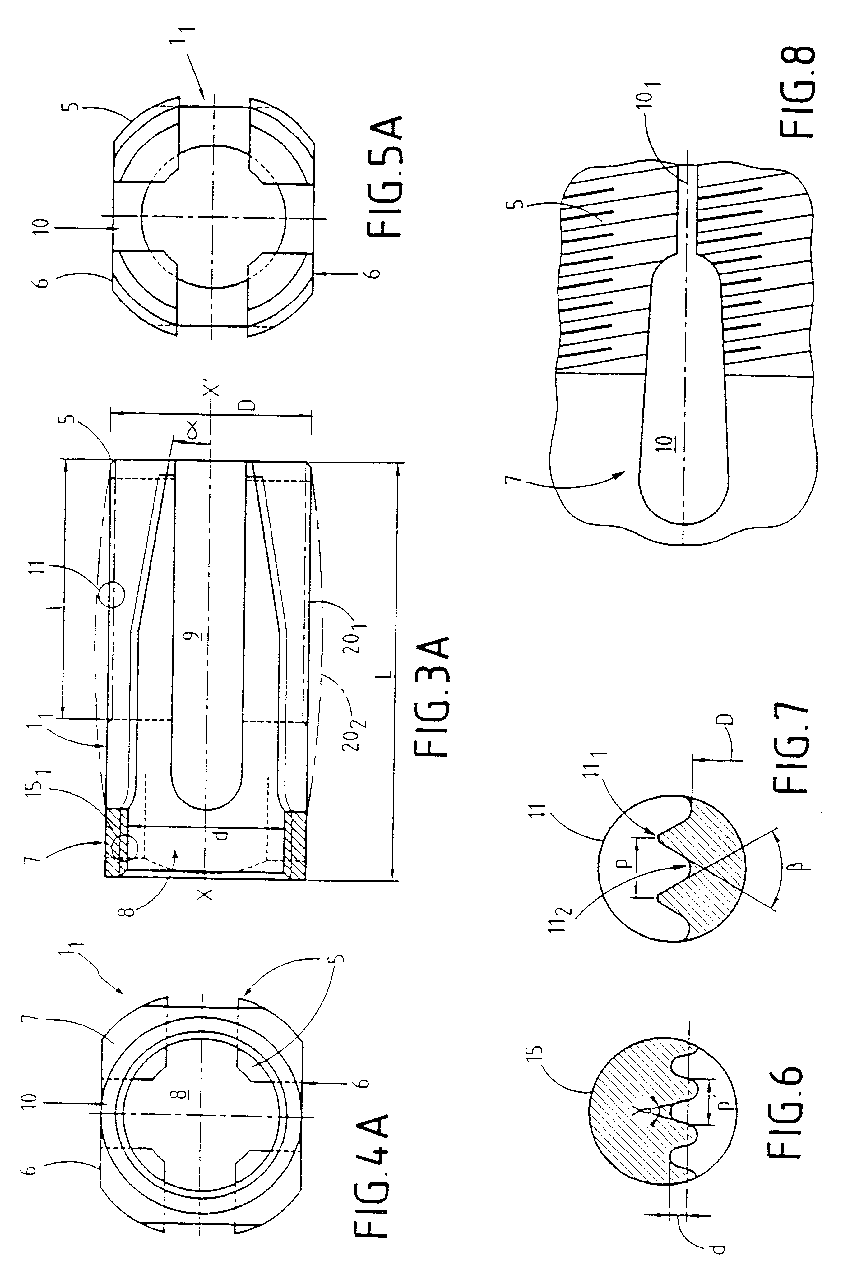
Whatever the embodiment, the expandable osteosynthesis implant comprises in conventional manner branches 5, each connected at one end to a seat 7 pierced by an orifice 8. According to an essential characteristic of the invention, said branches 5 and the seat 7 constitutes a hollow cage 1 which, in a "rest" position as shown for the embodiments of FIGS. 1, 3A, 4A, and 5A, and of FIGS. 9, 10, and 11, is of general outside shape that is cylindrical or quasi-cylindrical having a cross-section which is also the director curve of said cylinder that is circular or quasi-circular, with the generator line which engages said director curve and which generates the cylinder or quasi-cylinder by moving around its axis of symmetry XX' being either a straight line or a convex circular arc of large radius: this provides either a circularly-symmetrical right cylinder as shown in solid lines 20.sub.1 in FIG. 3A, or else a pseudo-cylinder referred to in the present specification as being "oval" or "ov...


PUM


Abstract

An expandable osteosynthesis implant has branches (5) each connected at one end to a seat (7) which is pierced by an orifice (8), suitable for being slid from a posterior direction between the facing faces of two consecutive vertebrae in order to hold them a given distance apart and restore stability of the spinal column. According to the invention, the branches (5) and the seat (7) define a hollow cage (1) which, in a "rest" position, has an outside general shape that is a cylinder of circular section, and a portion at least of the inside volume (9) of the cage (1) towards the distal ends of the branches (5) is in the form of a circular truncated cone whose large base is towards the seat (7), which implant has at least three branches (5) and, inside the inside volume (9) at least one spacer (2) suitable for passing through the orifice (8) and the large base of the truncated cone.

Description

The present invention relates to an expandable osteosynthesis cage.The technical field of the invention is that of implantable bone implants or prostheses and the surgical techniques for using them.The main application of the invention is to provide implants designed to be slid or inserted from a posterior direction between the facing faces of two consecutive vertebrae in order to maintain a given distance between them and to restore the stability of the spinal column, e.g. after a failure of the corresponding joint, by fixing the two vertebrae together.Several techniques are known at present for restoring a "normal" lumbar lordosis in this way, by implanting either a graft which in time fuses the vertebrae together, or a prosthesis which fixes them together immediately, while still also making it possible in time to achieve fusion between the vertebra.In the second above-mentioned technique, use is made mainly of implants, also known as "cages", some of which are hollow, rigid, and...

Claims


Application Information

Patent Timeline
Patent Type & Authority Patents(United States)
IPC IPC(8): A61F2/30A61F2/44A61B17/88A61F2/00A61F2/28A61F2/02A61F2/46A61B17/58
CPCA61F2/4455A61F2/446A61F2/30744A61F2/30724A61F2/442A61F2/4601A61F2/4611A61F2002/2835A61F2002/30112A61F2002/30143A61F2002/30154A61F2002/3021A61F2002/30217A61F2002/30225A61F2002/30235A61F2002/30253A61F2002/30332A61F2002/30367A61F2002/3037A61F2002/30377A61F2002/30403A61F2002/30405A61F2002/30421A61F2002/305A61F2002/30538A61F2002/30579A61F2002/30594A61F2002/30596A61F2002/30774A61F2002/30795A61F2002/3085A61F2002/4475A61F2220/0025A61F2220/0033A61F2230/0004A61F2230/0017A61F2230/0021A61F2230/0067A61F2230/0069A61F2230/0076A61F2250/0006A61F2002/30593A61F2/44A61F2/4637A61F2002/30115A61F2002/30224A61F2002/30622
Inventor CHAUVIN, JEAN-LUCATTALI, DAVIDATTIA, DAVID
Owner OSTEOIMPLANT TECH
Why Eureka
Try Eureka