Turbomachine nozzle with noise reduction

a technology of turbine nozzle and nozzle head, which is applied in the direction of machines/engines, transportation and packaging, aircraft power plants, etc., can solve the problems of unsatisfactory application of turbine technology to flow at a high subsonic rate, loss of aerodynamic performance, additional parasitic noise, etc., and achieves increased radial shear effect, increased outward deflection of flow, and increased shear

Active Publication Date: 2005-08-30
SN DETUDE & DE CONSTR DE MOTEURS DAVIATION S N E C M A
View PDF39 Cites 54 Cited by
  • Summary
  • Abstract
  • Description
  • Claims
  • Application Information

AI Technical Summary

Benefits of technology

[0005]The present invention thus seeks to mitigate such drawbacks by proposing a nozzle with separate flows, the nozzle enabling the noise of the jet to be reduced, in particular in a high subsonic regime, by encouraging mixing between the flows by creating shear and turbulence effects, while nevertheless satisfying the requirements to conserve flow rate and cross-sections around the entire circumference of the nozzle.
[0007]Thus, including negative and positive undulations on the inner barrel and on the centerbody makes it possible to generate a large amount of mixing between the primary and secondary flows. This large amount of mixing is obtained in particular by radial shear between the flows and by turbulence in the flows where they leave the nozzle. The undulations also make it possible to reduce the flow speeds along the longitudinal axis of the nozzle so as to accentuate mixing at the outlet from the nozzle. Furthermore, the primary and secondary flow rates are conserved and the cross-section remains constant around the entire circumference of the nozzle so that the aerodynamic performance of the nozzle is not affected by the undulations and any risk of local excess speed is avoided.
[0010]Advantageously, the arms are disposed in line with the negative undulations of the second series of undulations. Downstream from these negative undulations, the primary flow tends to go outwards from the wall of the conical portion of the centerbody, thereby generating radial shear between the flows. The presence of arms in line with the negative undulations enables this outward deflection of the flow to be increased and thus enables the radial shear effect to be increased.
[0011]According to an advantageous characteristic of the invention, the arms present means at a free end for generating additional radial shear between the primary and secondary flows. These additional shear means may be longitudinal slots forming an angle with the longitudinal axis of the nozzle and facing downstream therealong. The flow induced in the vicinity of these slots is thus deflected along the slots. Additional radial shear thus occurs between the flow in the vicinity of the slots (flow going away from the longitudinal axis of the nozzle) and the flow situated between the arms (flow going towards the longitudinal axis of the nozzle). The additional shear means may also be in the form of longitudinal fins that also serve to increase the shear in their vicinity and to reduce the speed of the flow along the longitudinal axis of the nozzle downstream from the arms.
[0012]According to another advantageous characteristic of the invention, the free end of the inner barrel includes, downstream from the first series of undulations, a series of tongues comprising negative tongues disposed in line with the negative undulations in the first series of undulations alternating with positive tongues disposed in line with the positive undulations in the first series of undulations. These tongues enable the amplitude of the shear between the primary and secondary flows to be increased, in particular at medium and high frequencies. The tongues interfere simultaneously in the primary and secondary flows. The deflections in the flow zones generated in this way beside the primary and secondary flows are the seat of a large amount of radial shear between the flows and strong mixing occurs between the flows between each of the flow zones defined by the tongues. By way of example, the tongues may present rounded U-shaped tips or pointed V-shaped tips.
[0013]According to yet another advantageous characteristic of the invention, the undulations of the second series of undulations present angular twist about the longitudinal axis of the nozzle so as to generate swirling in the primary flow. Such swirling together with the shear and the turbulence in the primary and secondary flows further increases mixing at the outlet from the nozzle and thus further reduces the amount of noise that is generated. The undulations in the first series of undulations preferably also present angular twisting that is equivalent to that of the undulations of the second series so as to generate swirling in the primary and secondary flows. Another way of generating swirling in the primary and secondary flows, in accordance with the invention, is to provide the each of the negative positive undulations of the first series of undulations with at least one notch or at least one deflector fin at an angle relative to the longitudinal axis of the nozzle.

Problems solved by technology

In a high subsonic regime, any local excess speed can lead to loss of aerodynamic performance, or to additional parasitic noise if a shockwave is produced.
Applying those technologies to a flow at a high subsonic rate is unsatisfactory.
The above-described requirements are not satisfied, and in particular the requirement relating to conserving constant cross-sections around the entire circumference of the nozzle.
This leads to local excess speeds which, in the high subsonic regime, generate shock waves which generate additional parasitic noise and which also reduce the aerodynamic performance of the nozzle.

Method used


Image

  • Turbomachine nozzle with noise reduction
  • Turbomachine nozzle with noise reduction
  • Turbomachine nozzle with noise reduction

Examples


first embodiment

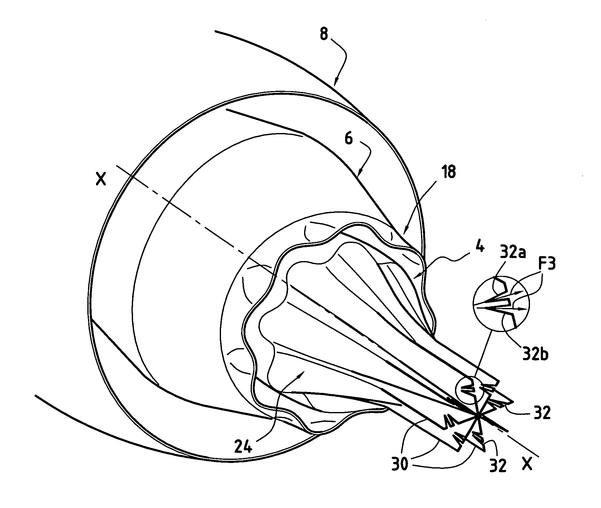
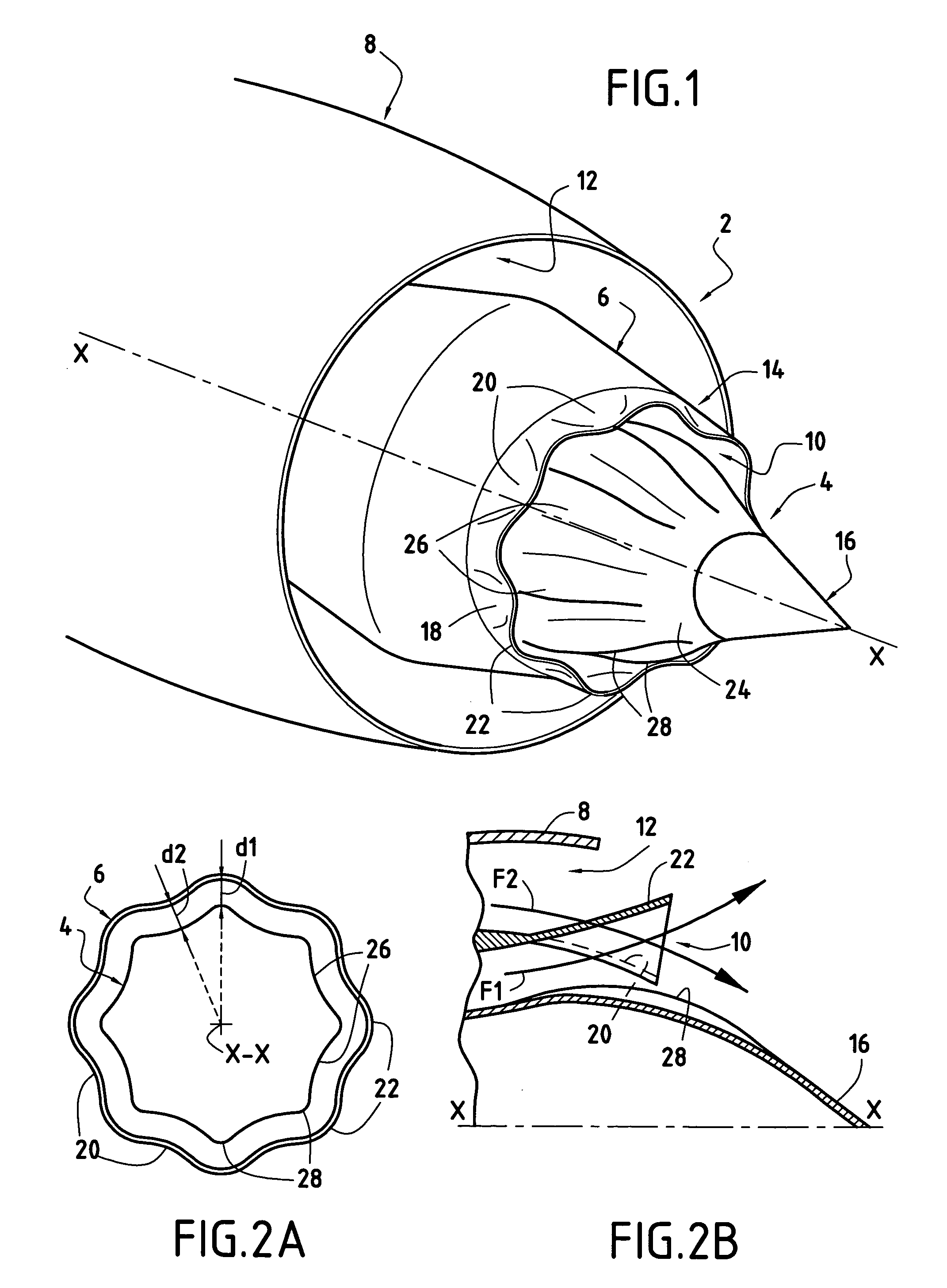
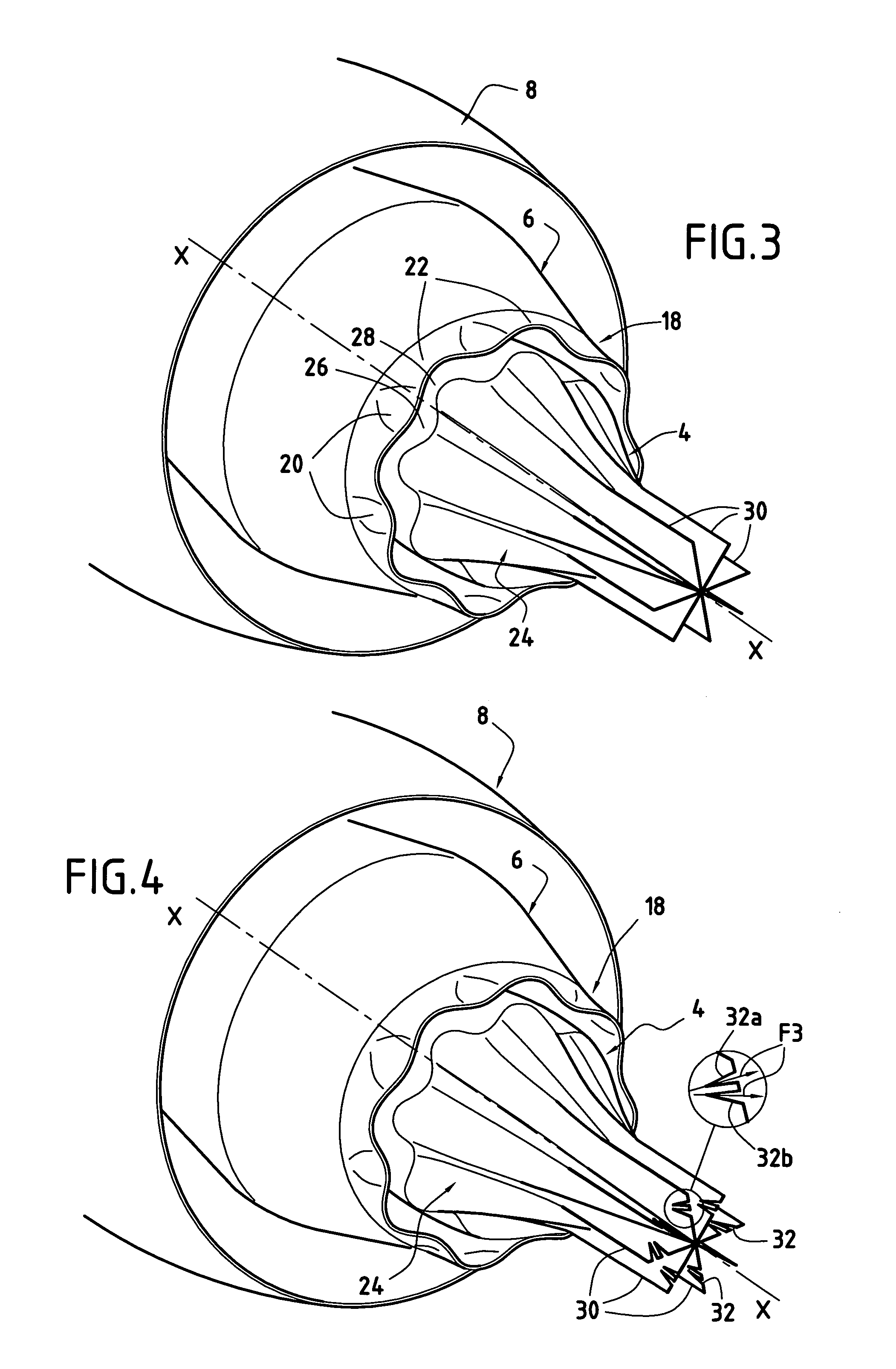
[0026]FIGS. 1, 2A, and 2B show a turbomachine nozzle constituting the invention. As explained above, this nozzle 2 is axially symmetrical in shape about a longitudinal axis X—X, and comprises a centerbody 4, an inner barrel 6, and an outer barrel 8 which are generally cylindrical in shape and are disposed concentrically relative to one another.

[0027]In FIG. 1, references 10 and 12 designate respectively the first annular channel for the primary flow and the second annular channel for the secondary flow of the turbomachine. The centerbody 4 of the nozzle is of the external type, i.e. its trailing edge extends longitudinally beyond a free end 14 of the inner barrel 6. It is terminated by a substantially conical portion 16. Furthermore, the outer barrel 8 of the nozzle shown in FIGS. 1 and 2B does not extend over the full length of the inner barrel 6. Nevertheless, the invention can also be applied to a nozzle in which the outer barrel extends over the entire length of the inner barrel...


PUM


Abstract

A nozzle comprising an inner barrel, a centerbody disposed inside the inner barrel so as to define a first channel for a primary flow, and an outer barrel surrounding the inner barrel so as to define a second annular channel for a secondary flow, the free end of the inner barrel presenting a surface having a first series of undulations made up of negative undulations alternating with positive undulations, the centerbody presenting a second series of undulations made up of negative undulations alternating with positive undulations, the negative and positive undulations of the series of undulations being of radial height that varies angularly and being disposed in such a manner that the negative undulations of the first series are disposed facing negative undulations of the second series, and vice versa, so as to generate turbulence and radial shear between the primary and secondary flows while conserving a constant flow section around the entire circumference of the nozzle.

Description

BACKGROUND OF THE INVENTION[0001]The present invention relates to the general field of nozzles fitted to turbomachines. More particularly, it seeks to reduce aerodynamic noise from the jet generated at the outlet of the nozzles of airplane turbomachines that deliver separate flows, and to do so in particular while such an aircraft is taking off.[0002]The nozzles fitted to airplane turbomachines generally comprise a centerbody surrounded by an inner barrel so as to form between them a first annular channel for a primary flow. An outer barrel surrounds the inner barrel so as to form a secondary annular channel for a secondary flow. The primary and secondary flows terminate, prior to being exhausted, in a converging portion, a throat, and a diverging portion. Overall these nozzle components are generally axially symmetrical in shape. The present invention relates more particularly to nozzles in which the centerbody is of the external type, i.e. having a trailing edge which is located d...

Claims


Application Information

Patent Timeline
Patent Type & Authority Patents(United States)
IPC IPC(8): F02K1/48F02K1/00
CPCF02K1/48
Inventor BARDAGI, THIERRYDRAVET, ALAINDOUSSINAULT, MARC
Owner SN DETUDE & DE CONSTR DE MOTEURS DAVIATION S N E C M A
Why Eureka
Try Eureka