Turboshaft engine with reduced noise emission for aircraft

a technology of aircraft and turbojet engine, which is applied in the direction of aircraft navigation control, marine propulsion, vessel construction, etc., can solve the problems of limited effect in noise generation, cost, mass and drag, etc., and achieve the effect of reducing shock cell noise and attenuating jet nois

Active Publication Date: 2013-10-01
AIRBUS OPERATIONS (SAS)
View PDF16 Cites 3 Cited by
  • Summary
  • Abstract
  • Description
  • Claims
  • Application Information

AI Technical Summary

Benefits of technology

[0008]It is an object of the present invention to improve such bosses to allow not only an attenuation in jet noise but also a reduction in shock cell noise.

Problems solved by technology

Since the speeds of said cold flow and of said airstream differ from one another, this results in inter-penetrating fluidic shear, which generates noise, known in aeronautical parlance as “jet noise”.
Aside from the fact that these known nozzles demand definitive special shapes which in general increase the cost, mass and drag, it should be pointed out that, although they are effective in attenuating jet noise by creating turbulence that encourages the cold flow and the exterior aerodynamic airstream to mix, they have only a very limited effect in reducing shock cell noise.

Method used


Image

  • Turboshaft engine with reduced noise emission for aircraft
  • Turboshaft engine with reduced noise emission for aircraft
  • Turboshaft engine with reduced noise emission for aircraft

Examples


Embodiment Construction

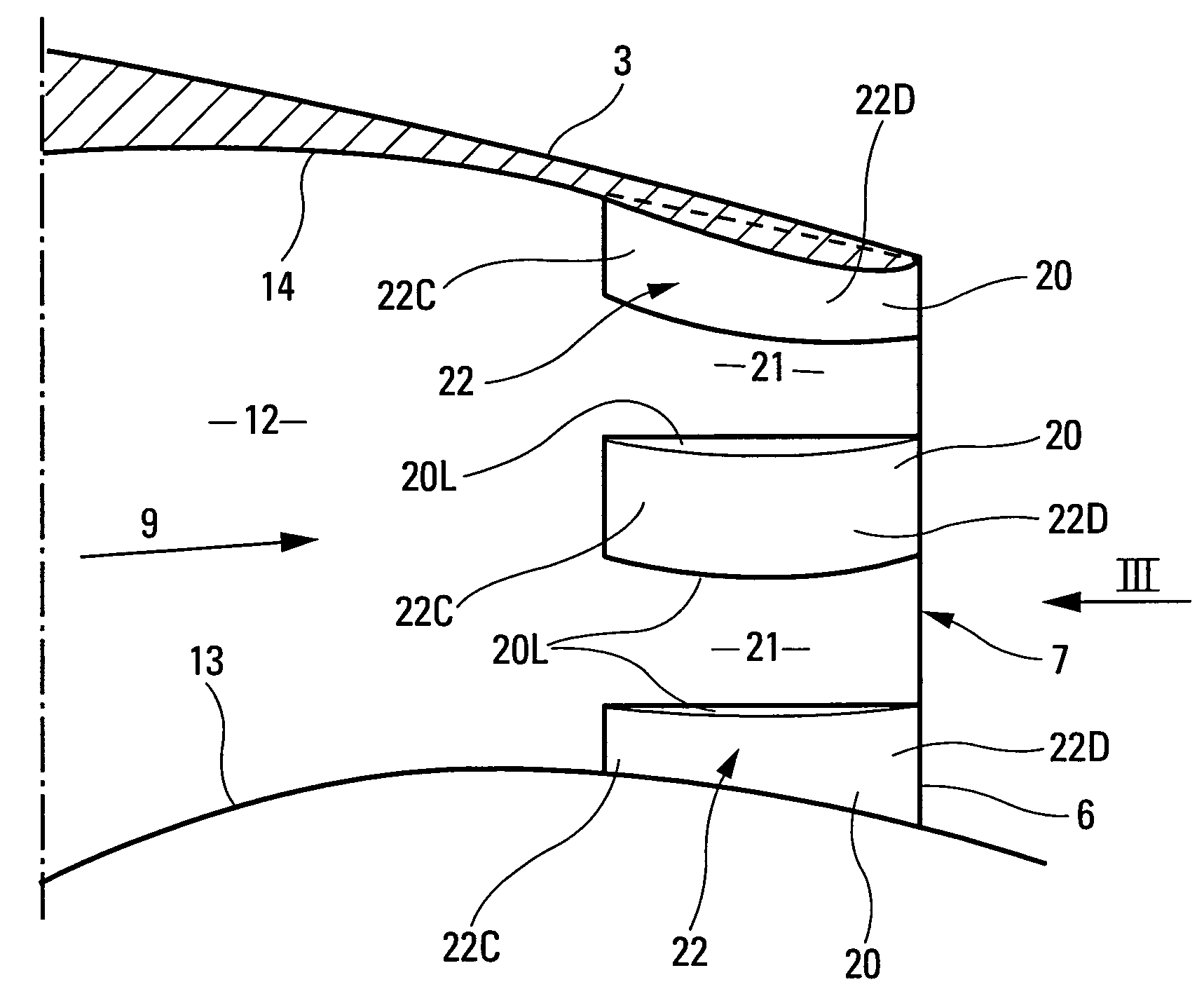
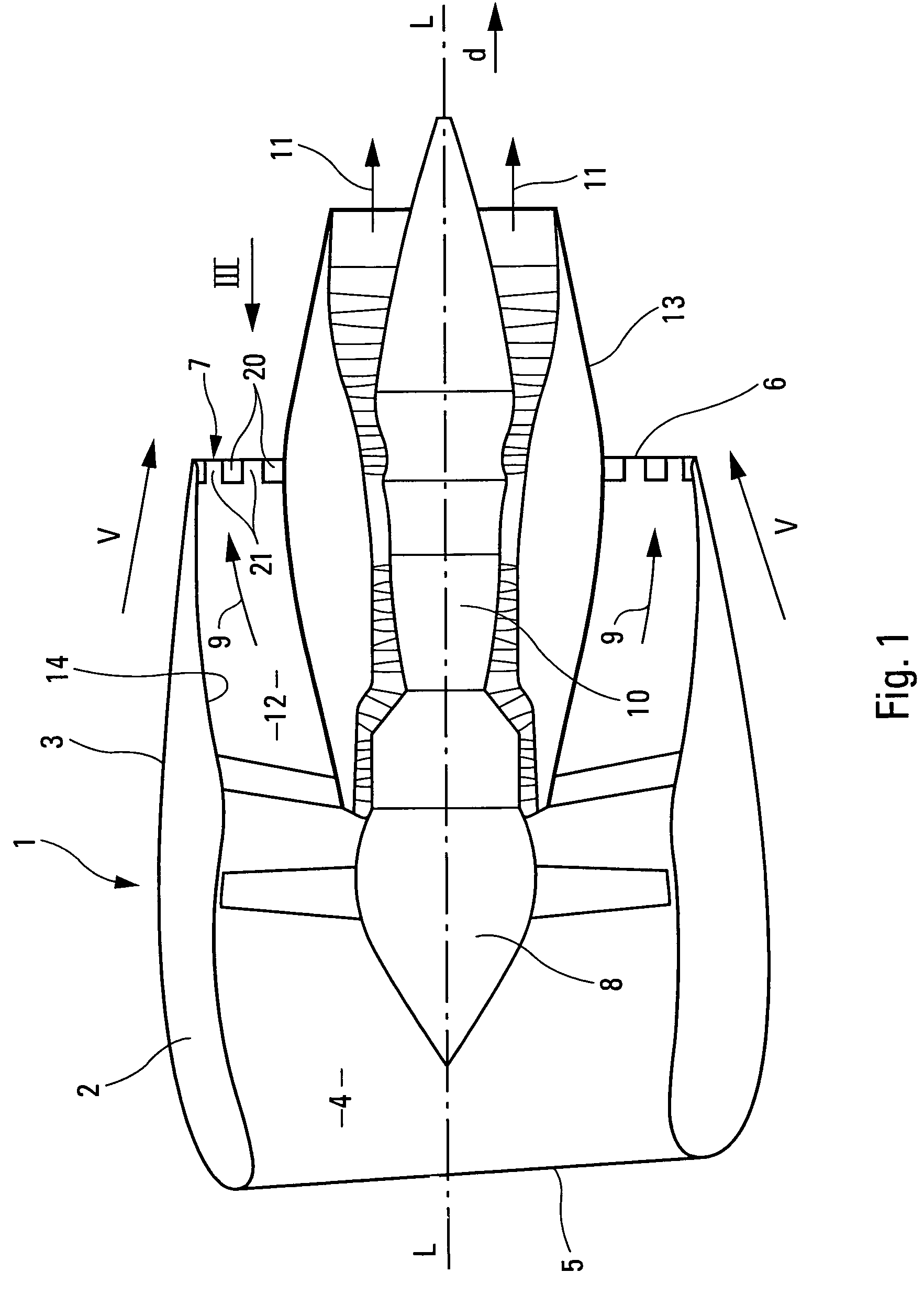
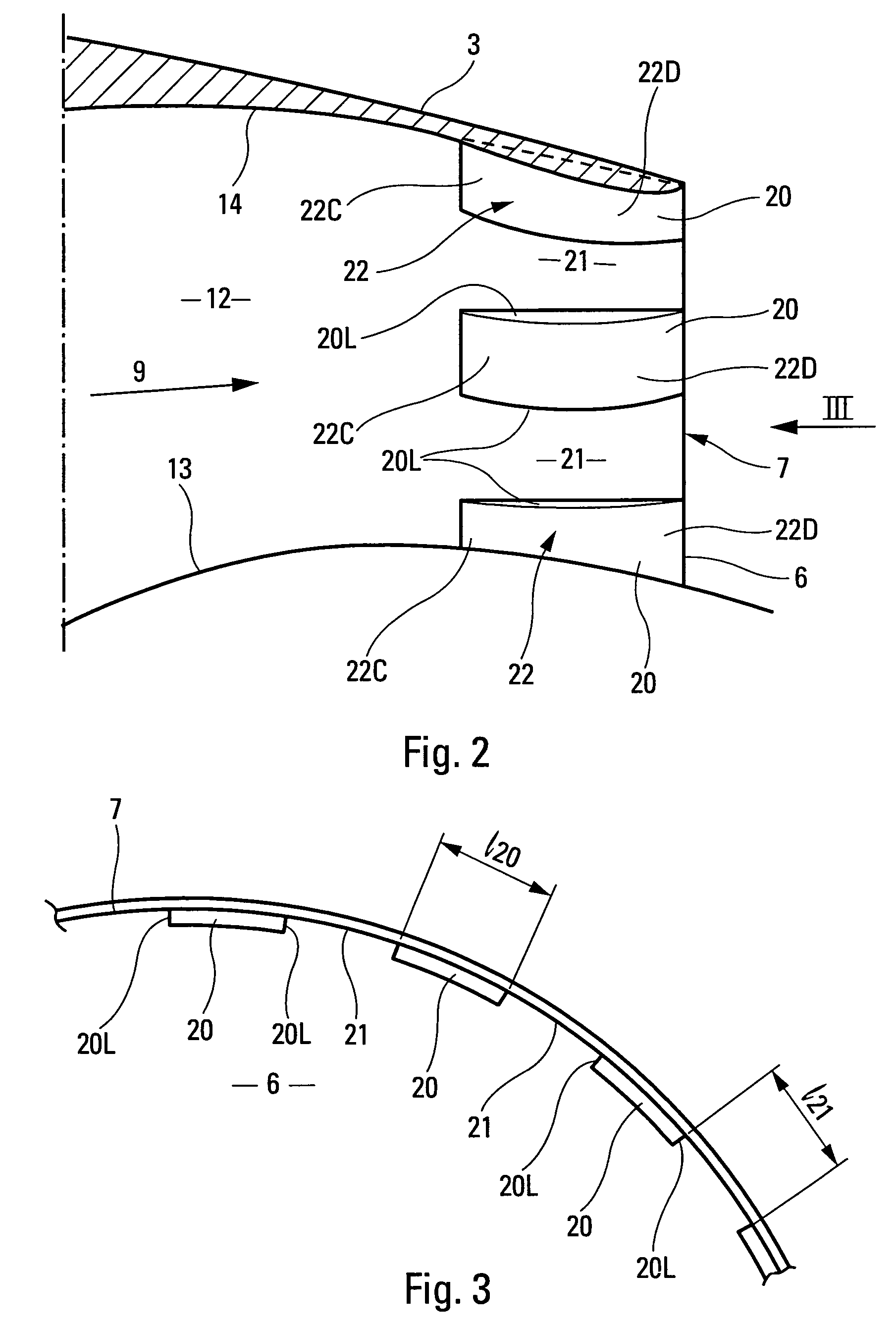
[0030]The bypass turbojet engine 1 of longitudinal axis L-L and shown in FIG. 1, comprises a nacelle 2 externally delimited by an outer nacelle cowl 3.

[0031]The nacelle 2 comprises, at the front, an air inlet 4 provided with a leading edge 5 and, at the rear, an air outlet orifice 6 provided with a trailing edge 7.

[0032]Positioned inside said nacelle 2 are:[0033]a fan 8 directed toward the air inlet 4 and able to generate the cold flow 9 for the turbojet engine 1;[0034]a central generator 10 comprising, in the known way, low-pressure and high-pressure compressors, a combustion chamber and low-pressure and high-pressure turbines, and generating the hot flow 11 of said turbojet engine 1; and[0035]an annular cold flow duct 12, created around said central generator 10, between an inner fan cowl 13 and an outer fan cowl 14.

[0036]The outer fan cowl 14 forms a nozzle for the cold flow and converges, toward the rear of the turbojet engine 1, toward said outer nacelle cowl 3, in order therew...


PUM


Abstract

According to the invention, a plurality of embossments (20) having a rectangular section is provided at the inner periphery of the outlet opening (7) of the fan duct (12), said embossments being separated by longitudinal channels (21) having a convergent (22C) and a divergent (22D) for the cold flow (9).

Description

CROSS-REFERENCE TO RELATED APPLICATIONS[0001]This application is a §371 national stage entry of International Application No. PCT / FR2008 / 001166, filed Aug. 4, 2008, which claims priority to French Patent Application 0705875, filed Aug. 17, 2007, the entire contents of which are incorporated herein by reference.FIELD OF THE INVENTION[0002]The present invention relates to a turbojet engine with reduced noise emissions for an aircraft.BACKGROUND OF THE INVENTION[0003]It is known that, at the rear of a bypass turbojet engine mounted on an aircraft, the supersonic cold flow, flowing in the downstream direction of said turbojet engine, comes into contact with the exterior aerodynamic airstream of said turbojet engine. Since the speeds of said cold flow and of said airstream differ from one another, this results in inter-penetrating fluidic shear, which generates noise, known in aeronautical parlance as “jet noise”.[0004]In addition, as a result of a discontinuity in static pressure betwee...

Claims


Application Information

Patent Timeline
Patent Type & Authority Patents(United States)
IPC IPC(8): F02K1/46
CPCF02K1/48Y02T50/671Y02T50/60
Inventor SYLLA, AMADOU ANDRECROSTA, FRANCKPELAGATTI, OLIVIERPRAT, DAMIEN
Owner AIRBUS OPERATIONS (SAS)
Why Eureka
Try Eureka