Gas ejection cone for an aircraft turbojet equipped with a device for generating turbulence in a primary flow limiting jet noise

Inactive Publication Date: 2011-08-25
AIRBUS OPERATIONS SAS
View PDF9 Cites 3 Cited by
  • Summary
  • Abstract
  • Description
  • Claims
  • Application Information

AI Technical Summary

Benefits of technology

[0015]Another advantage relative to the present invention lies in the fact that the presence of the device for generating turbulence does not require a modification of the geometric definition of the primary flow channel, such that it does not create a harmful impact on performance.
[0016]As previously mentioned, it is preferable to seek to generate one or several vortices at the downstream end of the hollow main body of the ejection cone so that these vortices then spread in the primary flow, toward the downstream. Due to their dynamics, these vortic

Problems solved by technology

In general, the implementation of chevrons is satisfactory in terms of observed noise reduction, but it is largely detrimental to the performance of the turbojet, due to the aerodynamic disturbance created on the primary, secondary and outside flows.
The harmful aerodynamic impact on the secondary

Method used


Image

  • Gas ejection cone for an aircraft turbojet equipped with a device for generating turbulence in a primary flow limiting jet noise
  • Gas ejection cone for an aircraft turbojet equipped with a device for generating turbulence in a primary flow limiting jet noise
  • Gas ejection cone for an aircraft turbojet equipped with a device for generating turbulence in a primary flow limiting jet noise

Examples


Embodiment Construction

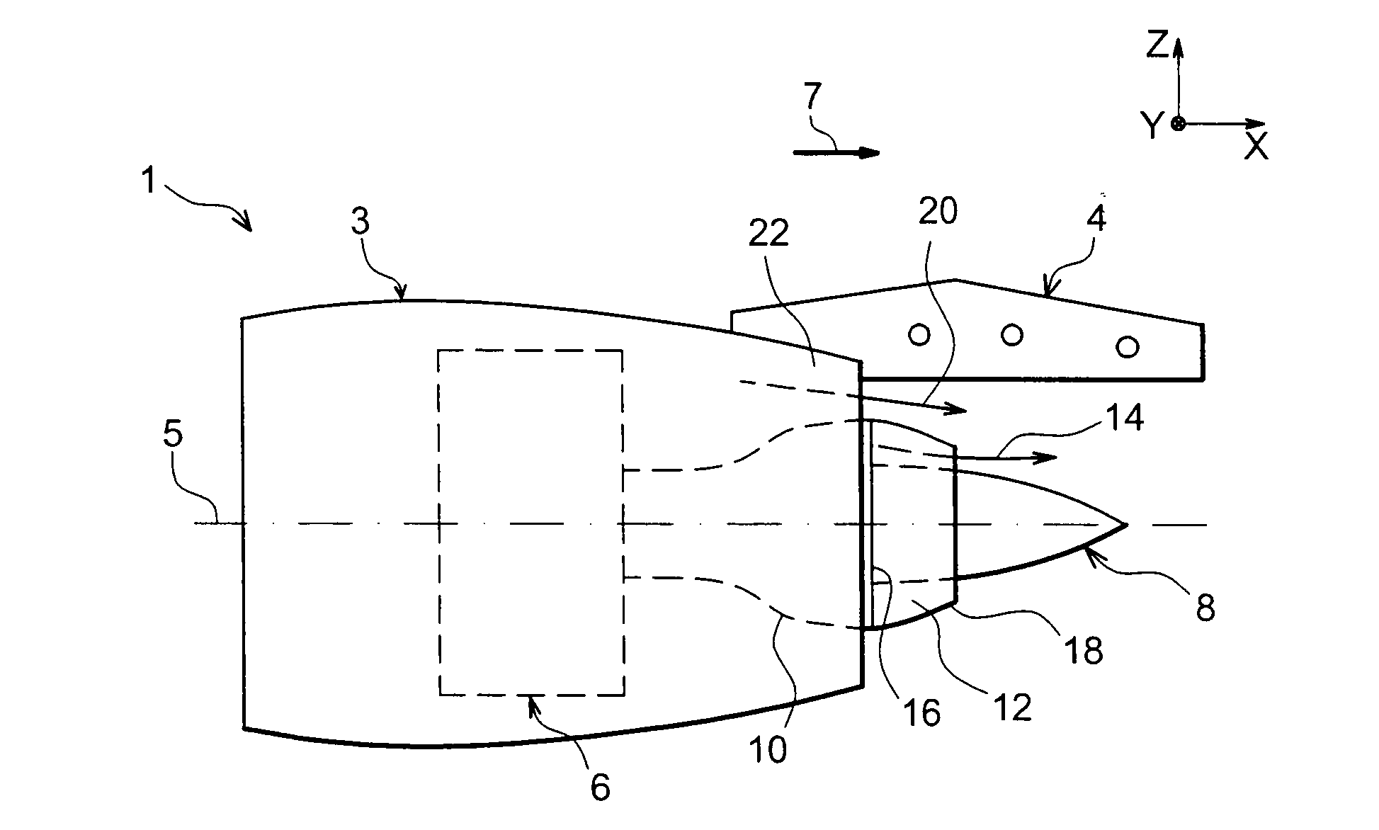
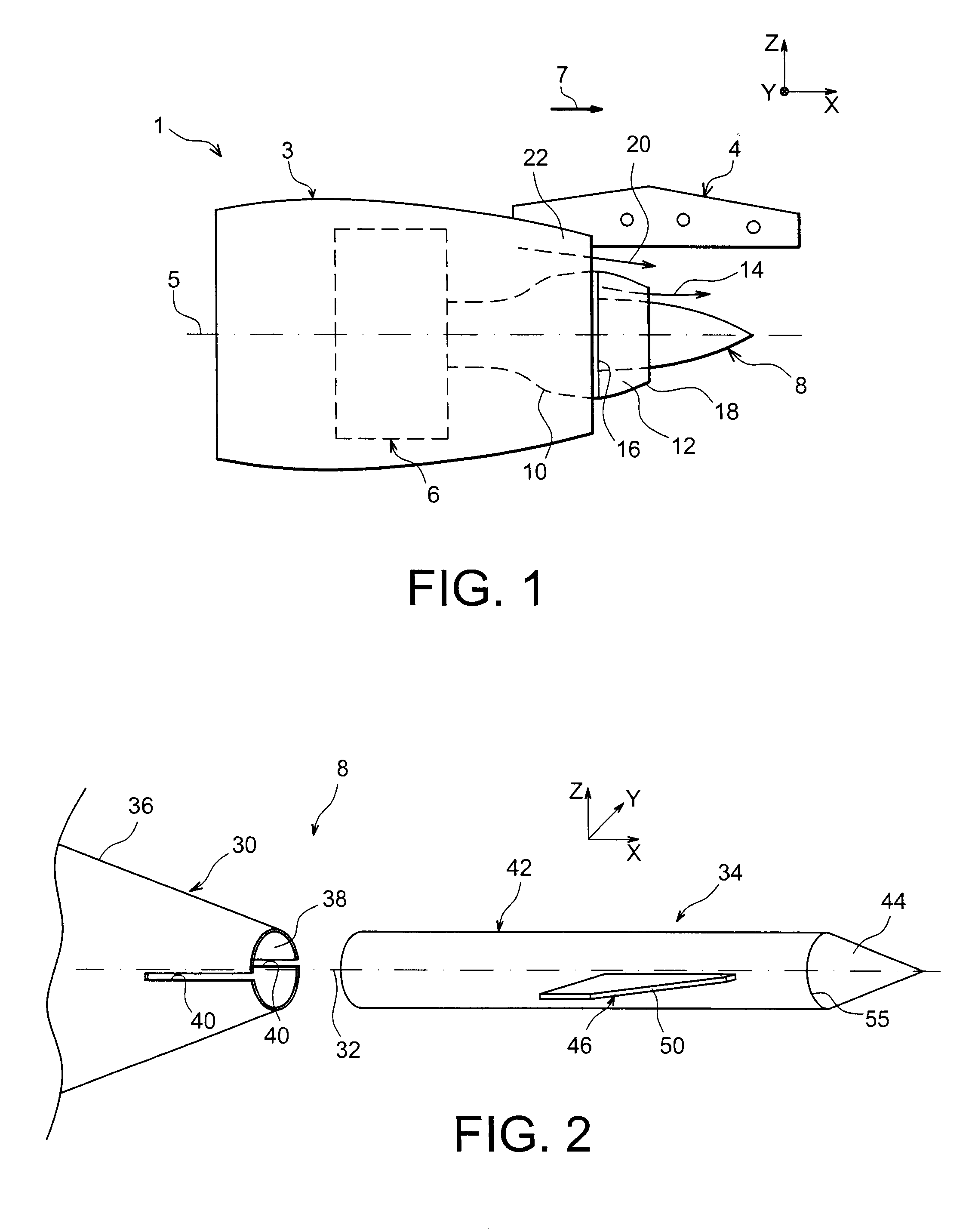
[0032]In reference first to FIG. 1, we see an engine assembly 1 for an aircraft designed to be fixed under a wing of this aircraft (not shown), this assembly 1 globally comprising an attachment device 4, a turbojet 6 such as a dual-flow turbojet with a high rate of dilution attached under this device 4, and a nacelle 3 surrounding the turbojet 6. Moreover, it comprises a gas ejection cone 8 (from the English “plug”) extending a crankcase 10, this cone 8 defining a radially inner skin of an annular primary flow 14 channel 12, centered on the longitudinal axis 5 of the turbojet 6.

[0033]In the entire description which follows, by convention, X designates the longitudinal direction of the device 4 which can also be likened to the longitudinal direction of the turbojet 6 and of its ejection cone 8, this direction X being parallel to the longitudinal axis 5 of this turbojet 6. Furthermore, Y designates the direction oriented transversely in relation to the device 4 and which can also be l...


PUM


Abstract

A gas ejection cone for an aircraft turbojet, the cone including a hollow main body defining, on the outside, a radially inner skin of an annular primary flow channel, and a device generating turbulence in the primary flow limiting jet noise, mounted so as to move on the main body so as to be able to be displaced from an extracted position in which the device projects toward downstream in relation to a downstream end of the hollow main body, and a retracted position in which the device is retracted into the hollow main body, and vice versa. Further, the device includes a cylindrical support body having an axis parallel to an axis of the ejection cone, and at least one fin supported by the body.

Description

TECHNICAL FIELD[0001]The present invention generally relates to an engine assembly for an aircraft comprising a turbojet having a crankcase, this assembly also comprising a gas ejection cone defining a radially inner skin of an annular primary flow channel, this ejection cone being fixedly mounted on a rear end of the crankcase. The invention also relates to such an ejection cone.[0002]The engine assembly according to the invention also comprises an attachment mast making it globally possible to suspend the turbojet below the wing system of the aircraft, or to mount this turbojet above this same wing assembly, or even to assemble this engine on a rear fuselage portion of the aircraft.BACKGROUND OF THE INVENTION[0003]The jet of an aircraft turbojet constitutes a relatively significant source of noise, which it is necessary to reduce in particular during the takeoff and landing phases of the aircraft, in order to best limit the noise nuisances suffered by airport inhabitants.[0004]In ...

Claims


Application Information

Patent Timeline
IPC IPC(8): F02K3/02F02K1/06
CPCB64D33/06F02K3/06F02K1/08F02K1/04
Inventor JOURNADE, FREDERICJOURNADE, JEROMEHUBER, JEROME
Owner AIRBUS OPERATIONS SAS
Why Eureka
Try Eureka