Variable-section flow mixer for a double-flow turbojet for a supersonic airplane

a turbojet and variable-section technology, which is applied in the direction of machines/engines, mechanical equipment, transportation and packaging, etc., can solve the problems of large reduction in noise level on takeoff, large lengthening of turbojets, and contradictory requirements, so as to reduce the noise level of turbojets during takeoff and reduce the thrust of turbojets

Active Publication Date: 2010-11-09
SN DETUDE & DE CONSTR DE MOTEURS DAVIATION S N E C M A
View PDF23 Cites 2 Cited by
  • Summary
  • Abstract
  • Description
  • Claims
  • Application Information

AI Technical Summary

Benefits of technology

[0010]A main object of the present invention is thus to mitigate such drawbacks by proposing a variable-section flow mixer that enables the jet noise level from the turbojet during takeoff to be decreased in a compact manner and without thereby decreasing the thrust from the turbojet.
[0012]The use of lobes having an azimuth component encourages mixing between the flow of air external to the turbojet and the flow of gas coming from the primary and secondary channels considerably by imparting gyratory motion to the external air. The presence of grooves in the central body further increases this mixing between the gas flows. In addition, all the grooves present an azimuth component in a direction opposite to that of the lobes, thereby enabling the flow of air set into gyration by the lobes to be “straightened out” by swirling it in the opposite direction. As a result, the thrust from the turbojet is not affected by the effect of the gyration imparted by the azimuth component of the mixer lobes.

Problems solved by technology

Unfortunately, those two requirements are contradictory.
Since jet noise increases with gas ejection speed, this reduction in speed leads to a large decrease in noise level on takeoff.
Although satisfactory, that solution presents the drawback of requiring the turbojet to be lengthened considerably in order to encourage mixing between the external air flow and the gas flow coming from the gas generator.
Unfortunately, the turbojet can be lengthened only to the detriment of its weight.
Although effective in reducing the jet noise level of turbojet on takeoff in compact manner, that solution nevertheless leads to a loss of thrust due to the gyration of the external air that is introduced into the turbojet when the lobes are in their open position.

Method used


Image

  • Variable-section flow mixer for a double-flow turbojet for a supersonic airplane
  • Variable-section flow mixer for a double-flow turbojet for a supersonic airplane
  • Variable-section flow mixer for a double-flow turbojet for a supersonic airplane

Examples


Embodiment Construction

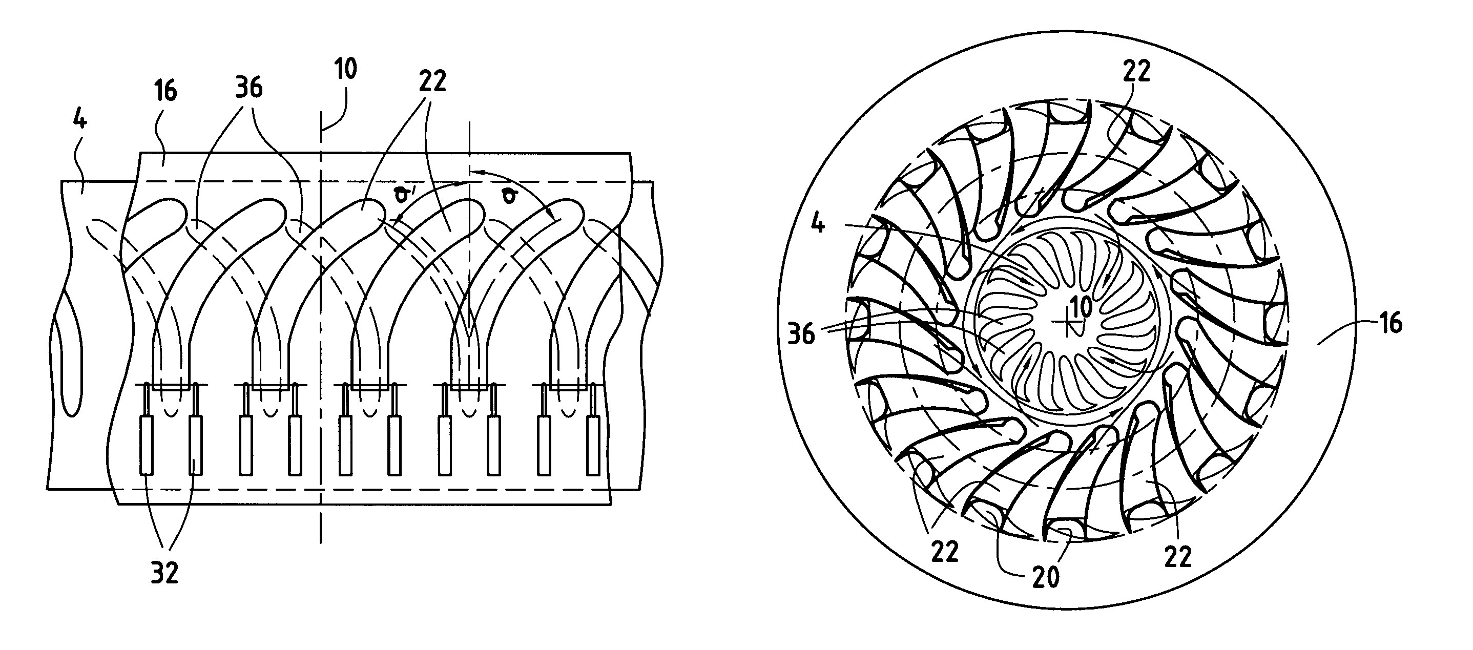
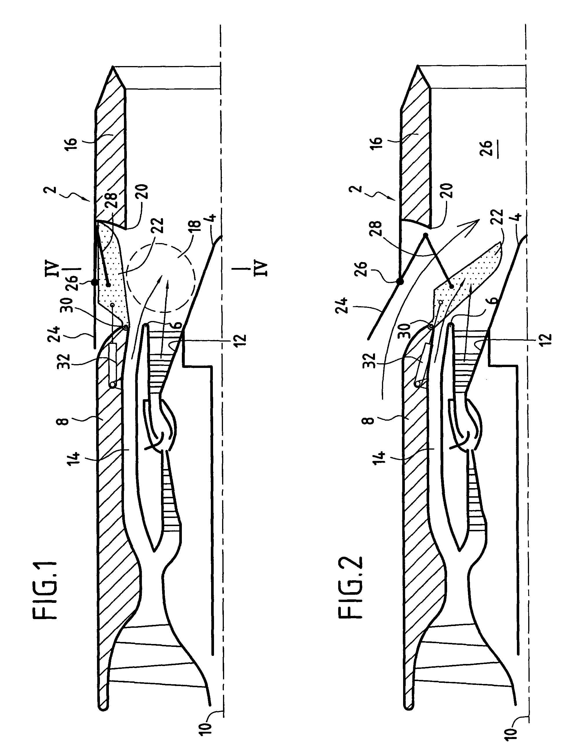
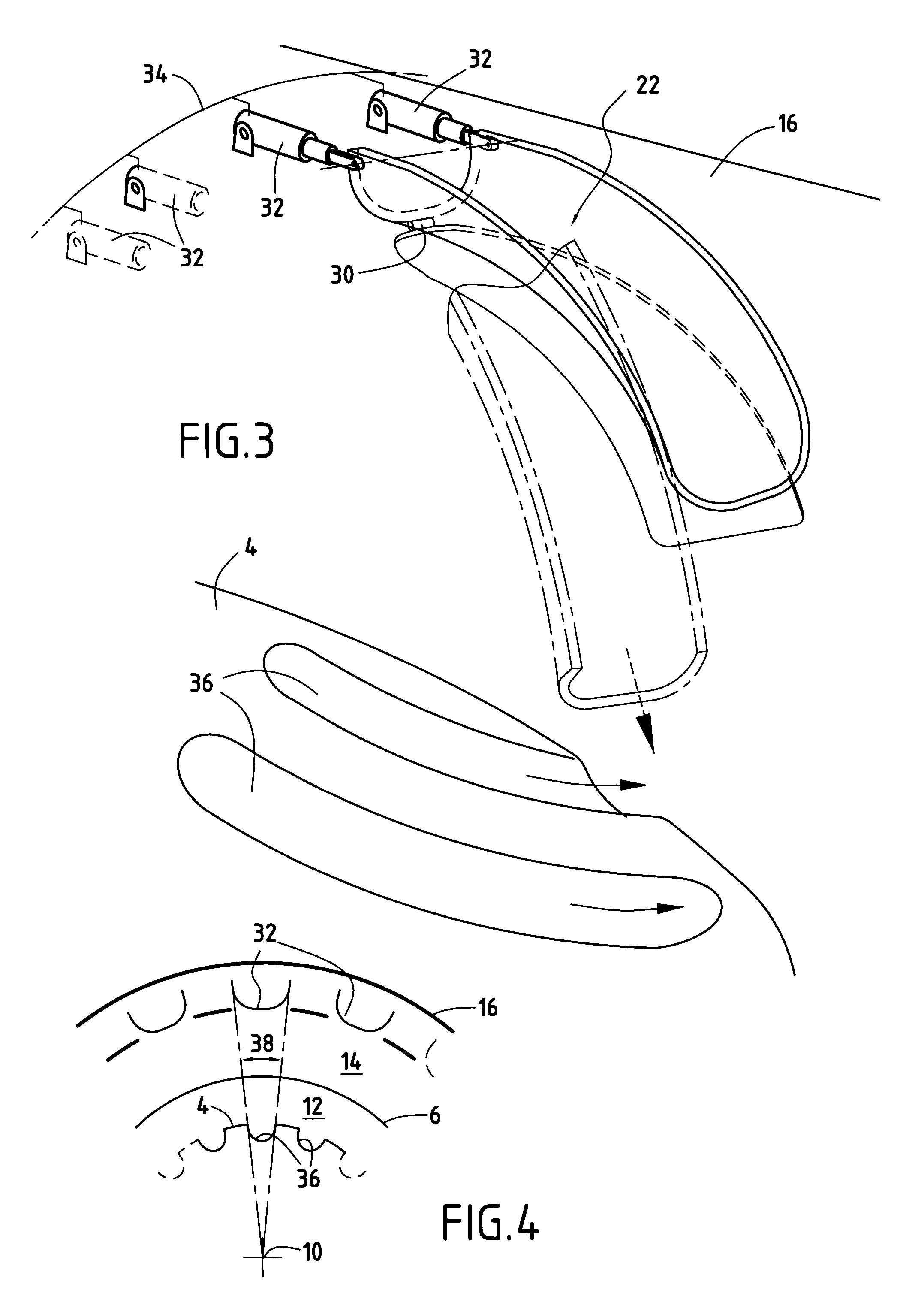
[0022]FIGS. 1 to 6 show a variable-section flow mixer of the invention. The mixer is intended in particular for fitting to a double-flow turbojet with a low bypass ratio for a supersonic airplane.

[0023]The mixer 2 mainly comprises a central annular body 4, a primary annular cover 6, and a secondary annular cover 8, all of these elements being centered on a longitudinal axis 10 of the turbojet.

[0024]The primary cover 6 surrounds the central body 4 coaxially so as to co-operate therewith to define a primary annular channel 12 for passing a hot gas flow coming from the turbojet.

[0025]The secondary cover 8 surrounds the primary cover 6 coaxially so as to co-operate therewith to define a secondary annular channel 14 coaxial about the primary channel and serving to pass a flow of cold air coming from the turbojet.

[0026]The mixer also includes an annular nozzle 16 for ejecting gas that is centered on the longitudinal axis 10 and placed longitudinally in line with the secondary cover 8. The...


PUM


Abstract

The invention relates to a variable-section flow mixer for a double-flow turbojet for a supersonic airplane, the mixer comprising a central body, a primary cover, a secondary cover, and a nozzle extending the secondary cover. The nozzle has a plurality of external-air admission openings having mounted therein lobes that are movable between two positions: a closed position in which they close the openings; and a deployed position in which they disengage said openings and deploy into the nozzle so as to allow external air to be admitted. All of the lobes present a common azimuth component in a common direction, and the mixer further includes a plurality of longitudinal grooves occupying at least a portion of the central body, all of the grooves presenting a common azimuth component in a common direction that is opposite to the direction of the azimuth component of the lobes.

Description

BACKGROUND OF THE INVENTION[0001]The present invention relates to the general field of variable-section flow mixers for double-flow turbojets with a low bypass ratio for supersonic airplanes.[0002]The low bypass ratio double-flow turbojet for a supersonic airplane essentially comprises a double-flow gas generator (generating a cold flow and a hot flow), extended by a nozzle that defines a gas ejection channel.[0003]Low bypass ratio double-flow turbojets for fitting to supersonic airplanes for use in civilian transport need to comply with two requirements: firstly they must present as little drag as possible during stages of transonic and supersonic cruising flight; and secondly they must present acceptable levels of noise on airplane takeoff, with certification authorities having increasingly more stringent requirements with respect to the emission of noise from the turbojets of civil airplanes.[0004]Unfortunately, those two requirements are contradictory. The first requirement lead...

Claims


Application Information

Patent Timeline
Patent Type & Authority Patents(United States)
IPC IPC(8): F02K1/00
CPCF02K1/383F05D2250/15Y02T50/671Y02T50/60
Inventor DUSSILLOLS, LAURENT CHRISTOPHELONGEVILLE, OLIVIER ROLANDVUILLEMIN, ALEXANDRE ALFRED GASTON
Owner SN DETUDE & DE CONSTR DE MOTEURS DAVIATION S N E C M A
Why Eureka
Try Eureka