Programmable electronic locking device

a technology of electronic locking and cylinder, applied in the direction of program control, testing/monitoring control system, instruments, etc., can solve the problems of limiting practical application, difficult to implement cylinders, and high cost of locks, and achieve the effect of simple and cheap

Inactive Publication Date: 2001-12-18
ELECTRONICS KEY SYST E K S R L
View PDF29 Cites 122 Cited by
  • Summary
  • Abstract
  • Description
  • Claims
  • Application Information

AI Technical Summary

Benefits of technology

An object of the present invention is to mitigate the above-specified drawbacks by providing a programmable electronic closure device that is particularly simple and cheap and capable of being implemented by any user, even if not professional.

Problems solved by technology

Such cylinders are particularly complex to implement and they often make it possible to obtain several billion different combinations, with the best of them presenting excellent resistance to picking and to drilling.
Nevertheless, each of the above-specified locks suffers from a major drawback in that their security depends essentially on the type of mechanical cylinder used for receiving the keys, with the electronic device providing no more than an additional security element.
Maximum security is provided above all by the cylinder being of complex structure, with the consequence of the lock being very expensive.
Nevertheless, that electronic locking system still suffers from certain drawbacks, in particular in the event of the key being lost or in the event of the power supply running low, thereby greatly restricting practical application thereof and, in fact, making it unsuitable for any commercial use.
However, under such circumstances, the complexity of the resulting system makes it particularly expensive and difficult to use for a non-professional user.

Method used


Image

  • Programmable electronic locking device
  • Programmable electronic locking device
  • Programmable electronic locking device

Examples


first embodiment

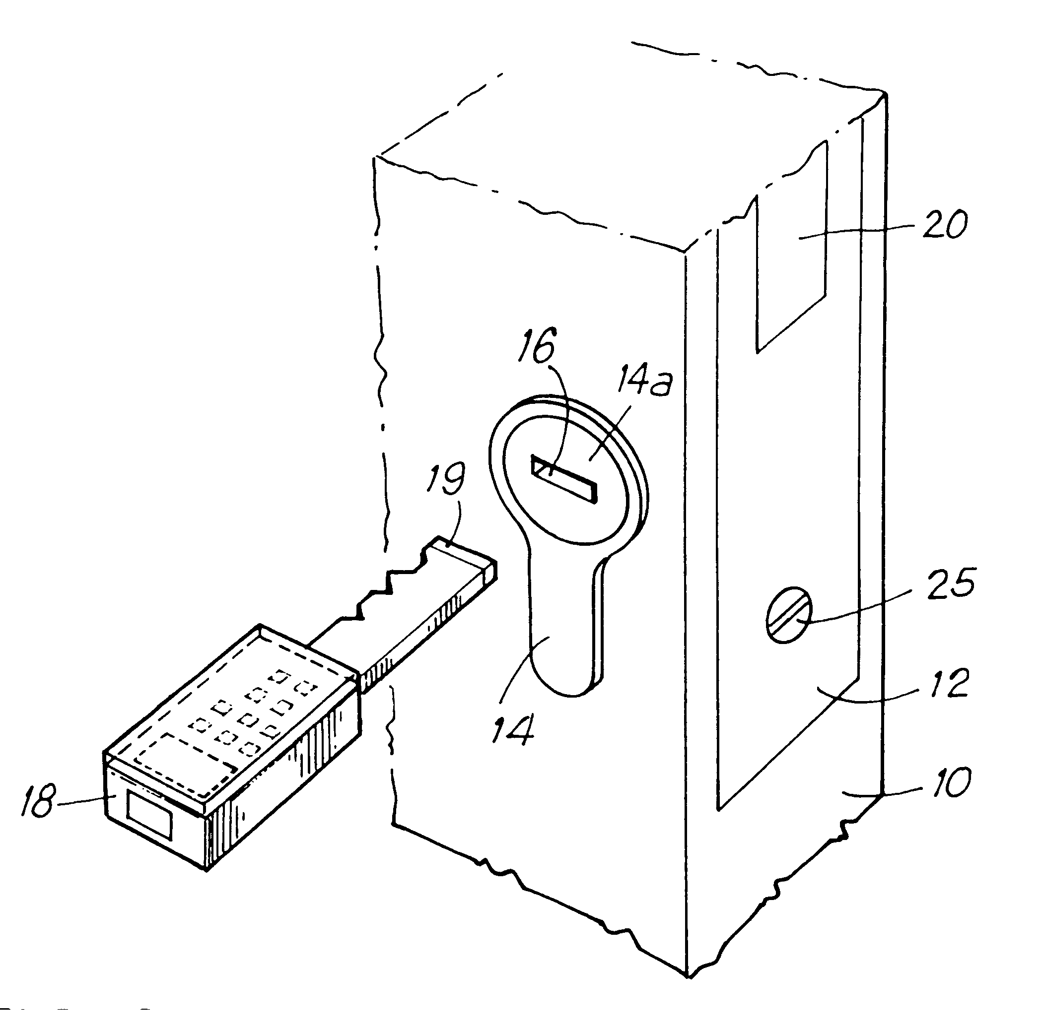
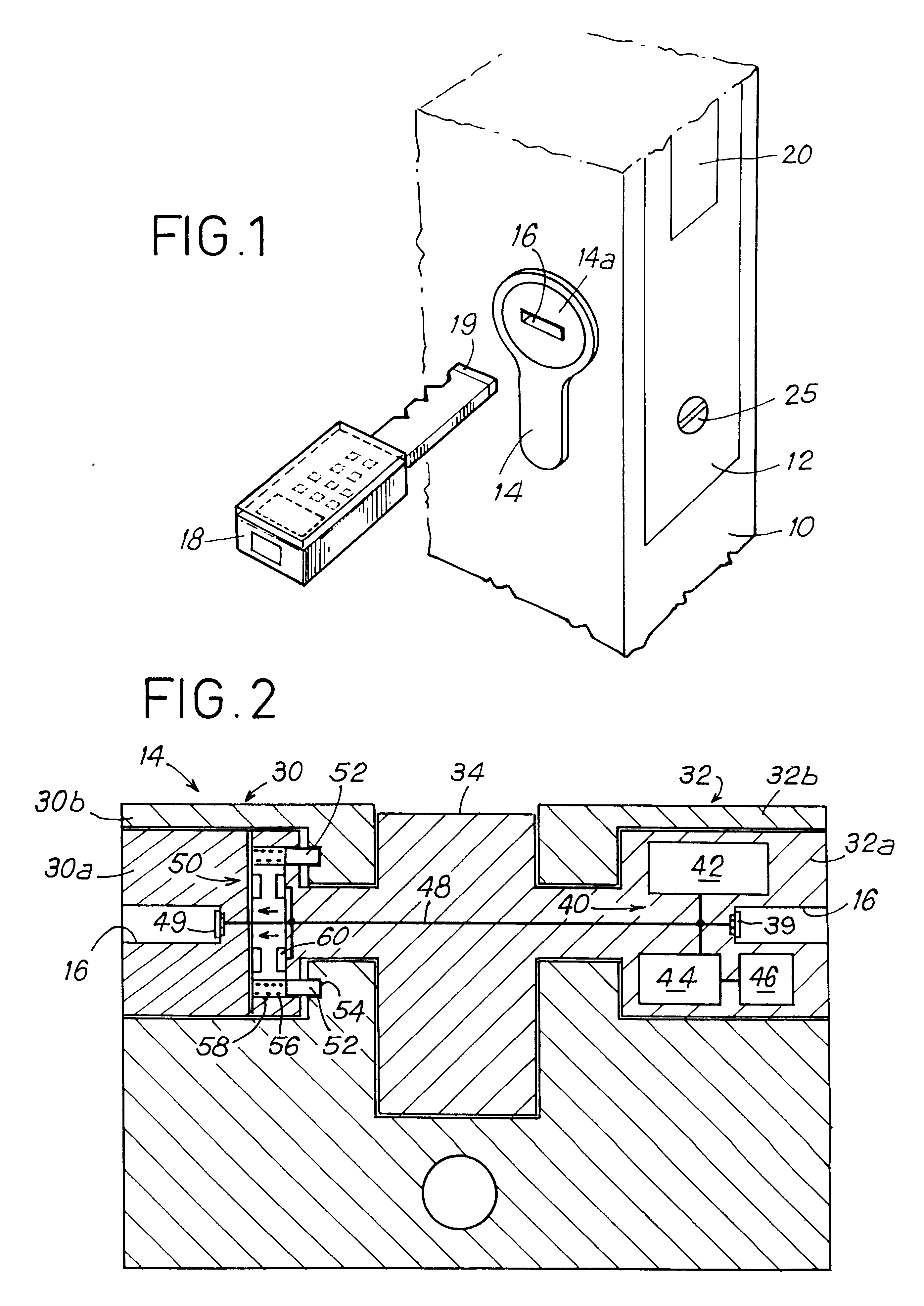
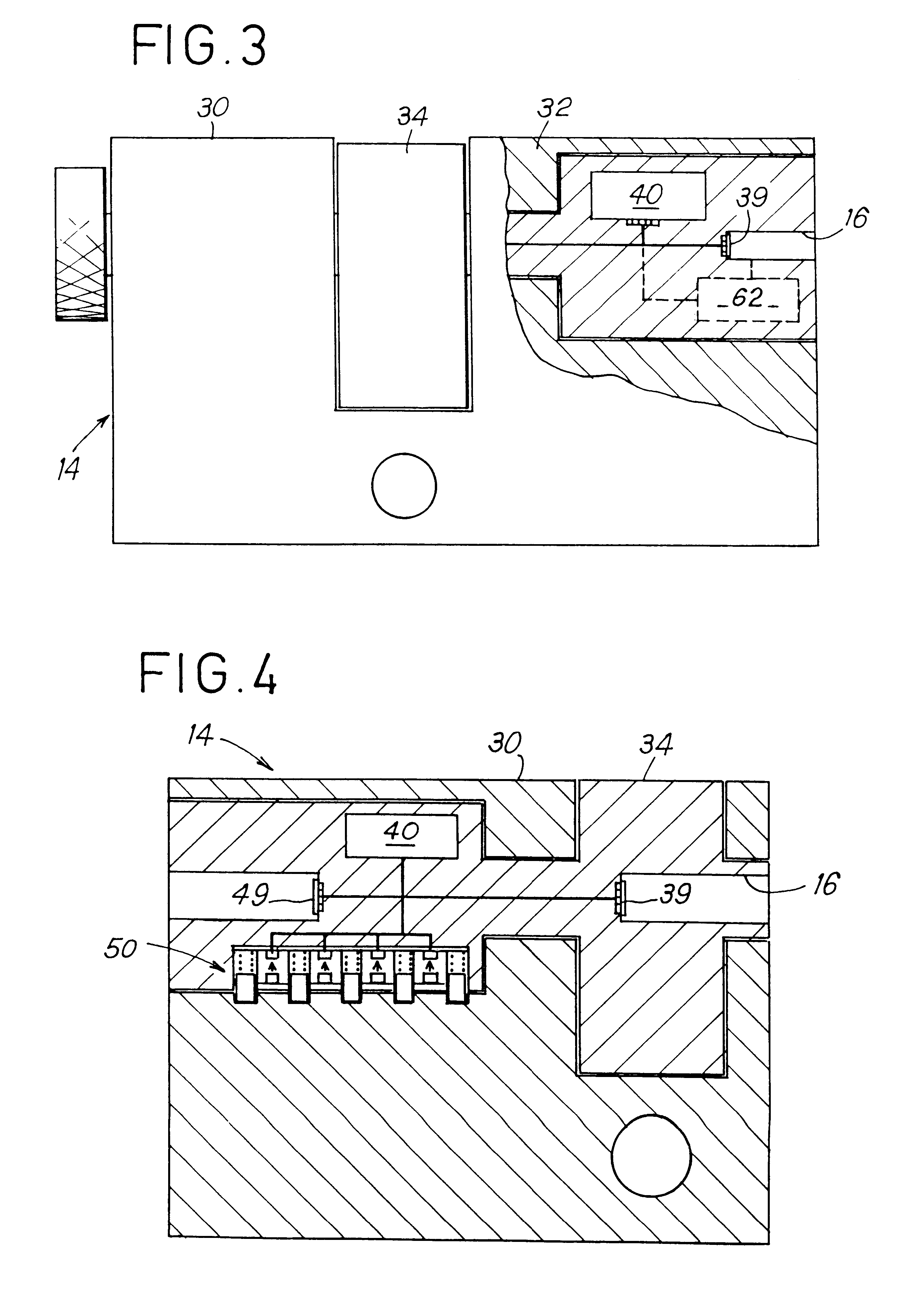
the electronic key 18 is now described in detail with reference to FIGS. 5 to 7. This key is mainly constituted by two portions 18A and 18B, and at one end it includes a flat rod provided with the first electrical connection means 19 that is constituted by a set of individual contacts (comprising, for example, a ground contact and a single data contact) designed to co-operated with corresponding contacts of the second electrical connection means 39 present in the keyway 16 of the lock, and at its opposite end the key has a head of arbitrary shape that may advantageously be parallelepipedal, and that includes both a display 86 and a keypad 80 provided with a set of function keys 82 and digit keys 84 all of which are protected by a closable flap that protects the display and the keypad except while programing is being performed. Advantageously, additional connection means 29 may be provided to connect the key to an external programming module. Although the contacts in the example show...


PUM


Abstract

A programmable electronic closure system has a lock for operation by a key when an identification code of the key and a corresponding code of the lock match. The closure system can be programmed to modify the code data in both the key and the lock using an input device.

Description

The present invention relates to the field of electronic or mechanical-and-electronic locks, and to associated security combination keys.PRIOR ARTAt present, in dwellings, and more generally in local or professional premises there exist numerous types of mechanical lock designed to be received in the moving part of a door or of a gate and in which the cylinder complies, dimensionally, with European or international standards that are in force. Such cylinders are particularly complex to implement and they often make it possible to obtain several billion different combinations, with the best of them presenting excellent resistance to picking and to drilling.There also exist on the market very many locking devices based on a system comprising a lock and a key, e.g. for cars (steering-column locks) or more generally in industry, in particular for authorizing or preventing operation of numerous appliances or indeed of electronic cabinets or racks.Over the last few years, there have also ...

Claims


Application Information

Patent Timeline
Patent Type & Authority Patents(United States)
IPC IPC(8): G07C9/00E05B49/00
CPCG07C9/00817G07C9/00857G07C2009/00761G07C2009/00841Y10T70/7791Y10T70/7441E05B49/00
Inventor DAWALIBI, NOFAL
Owner ELECTRONICS KEY SYST E K S R L
Why Eureka
Try Eureka