Assembly system based on a ball anchoring device

Inactive Publication Date: 2005-01-11
FAURECIA
View PDF24 Cites 23 Cited by
  • Summary
  • Abstract
  • Description
  • Claims
  • Application Information

AI Technical Summary

Benefits of technology

The present invention therefore aims at providing an attachment system that is simpler and less costly than the separable anchoring systems described above, but which is rapid and easy to implement and can be readily automated, without presenting, for example, the above mentioned disadvantages of screwing attachment systems. It aims in particular at proposing an attachment system that can be installed by a robot, with few components and therefore reduced manufacturing cost. It also aims

Problems solved by technology

Consequently, it is obligatory to perform a screwing operation when putting the seat in place in the vehicle, which is not always practical if the bolt heads or nuts are poorly accessible to conventional screwing tools.
This means that the pin cannot return to its locking position as long as the said ring has not been pushed back by the floor when the tubular body is inserted into the hole in the floor, when the seat is put back into its utilization position.
As can be seen,

Method used


Image

  • Assembly system based on a ball anchoring device
  • Assembly system based on a ball anchoring device
  • Assembly system based on a ball anchoring device

Examples


Example

Refer to the appended drawings in which:

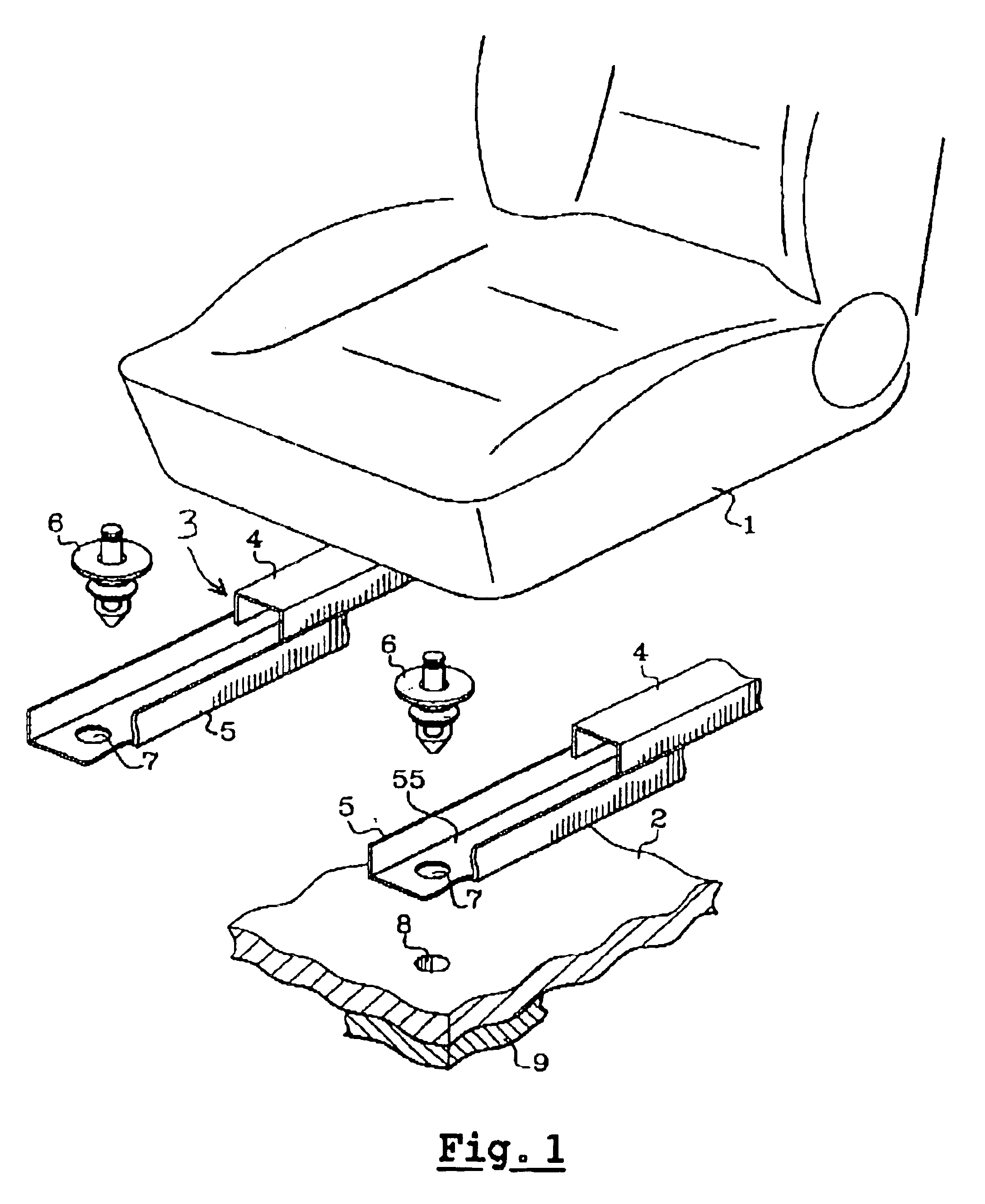
FIG. 1 is a partial perspective and exploded view of the seat and the elements for assembling it to the floor,

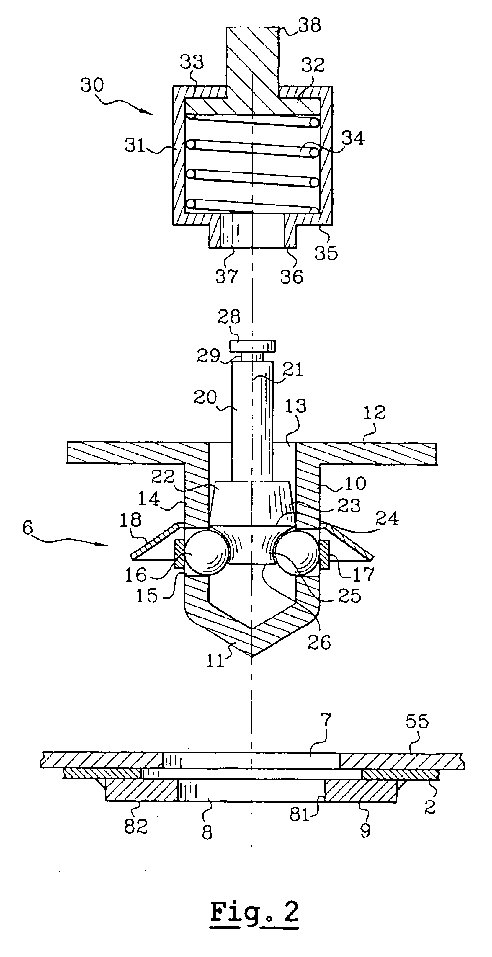
FIG. 2 is a cross-sectional view of the attaching device before installation, offered up above the parts to be assembled, along with the installation tool,

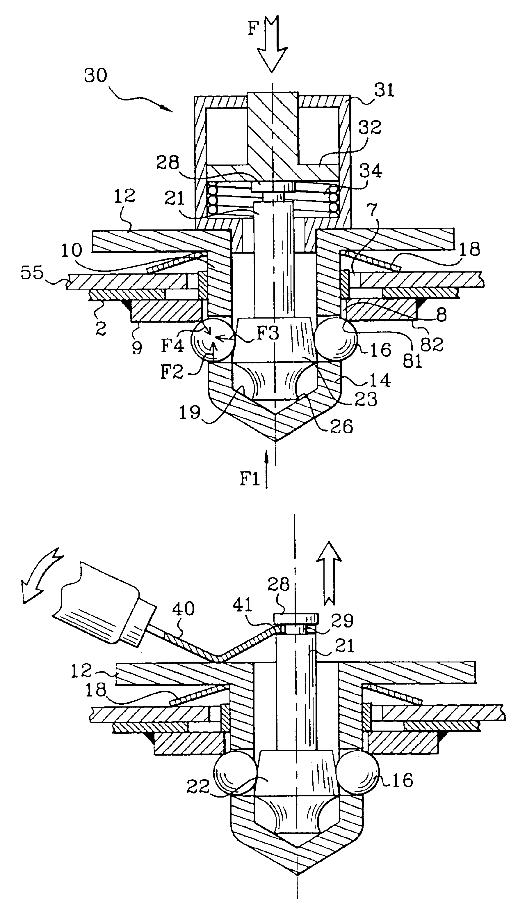
FIGS. 3 to 5 illustrate the subsequent phases in the making of the assembly,

FIG. 6 illustrates the removal of the attaching device,

FIG. 7 provides a similar view to FIG. 2, in another embodiment, where the device is premounted on the first part to be assembled.

BRIEF DESCRIPTION OF THE INVENTION

The drawing in FIG. 1 shows a vehicle seat 1 that is to be mounted on the floor 2 of the said vehicle by means of a set of rails 3 allowing longitudinal adjustment of the seat position. In a way known in itself, the frame of the seat pan is fixed to the upper rail elements 4, and the seat is usually supplied with its set of rails ready to be mounted on the floor 2. The lower rail elements 5 are...


PUM


Abstract

The ball anchoring device consists of a lock body (10) comprising an annular wall (14) featuring radial holes (15) to accommodate radially mobile balls (16), and a locking piston (20) that slides axially within the body bore between a released position and a locked position.
The lock body (10) is inserted into a first hole (7) made in the surface of the first part (55) and into a second hole (8) made in the surface of the second part, the two holes being more or less coaxial. It features a flange (12) bearing against the first part around the first hole through a spring thrust element (18), and with the piston in the locked position, the balls (16) are maintained partly protruding under the free face (82) of the second part, on the one hand in angular contact with the edge (81) of the second hole (8), and on the other hand bearing against a lateral retention surface (23) of the piston head (22), under the effect of the axial thrust applied to the balls by the body through the load applied to the flange (12) by the spring thrust element (18).

Description

FIELD OF THE INVENTIONThis invention concerns an attaching system of the ball lock type, which can be used more particularly, but not exclusively, to attach an automobile vehicle seat supporting structure to the floor of the said vehicle.BACKGROUND OF THE INVENTIONTo make such an attachment, for example to secure to the floor a rail element for longitudinal seat position adjustment, a means of attachment by screwing is commonly used, either by screwing a bolt into a nut joined to the floor, or screwing a nut onto a threaded stud joined to the said floor. Consequently, it is obligatory to perform a screwing operation when putting the seat in place in the vehicle, which is not always practical if the bolt heads or nuts are poorly accessible to conventional screwing tools.In other cases, particularly when the connection of the seat to the floor must be readily separable, for example in the case of the rear attachments of seats with tilting seat pans, or with completely removable seats,...

Claims


Application Information

Patent Timeline
IPC IPC(8): F16B19/10F16B19/04F16B21/00
CPCF16B19/109Y10S403/06Y10T403/599Y10T403/592Y10T403/591Y10T403/7123Y10T292/14
Inventor BLANCHARD, JEAN-MARIE
Owner FAURECIA
Why Eureka
Try Eureka