
Hybrid frequency contactless transponder unit, module for and method of manufacturing

a technology of contactless transponder and module, which is applied in the field of contactless transponder module, contactless transponder module, etc., can solve the problems of not being able to operate in several frequencies at the same time, not being able to show the structure of such transponders in documents, and never reaching mass production volume of products. , to achieve the effect of improving the known manufacturing techniques of hybrid frequency contactless transponder units

Inactive Publication Date: 2007-08-23
ASSA ABLOY AB
View PDF9 Cites 20 Cited by
  • Summary
  • Abstract
  • Description
  • Claims
  • Application Information

AI Technical Summary

Benefits of technology

[0019] It is therefore one aim of the present invention to improve hybrid frequency contactless transponder units and also to improve the known techniques of manufacturing such units.
[0020] It is another aim of the present invention to provide a simple and cheap chip module for hybrid frequency transponder units.
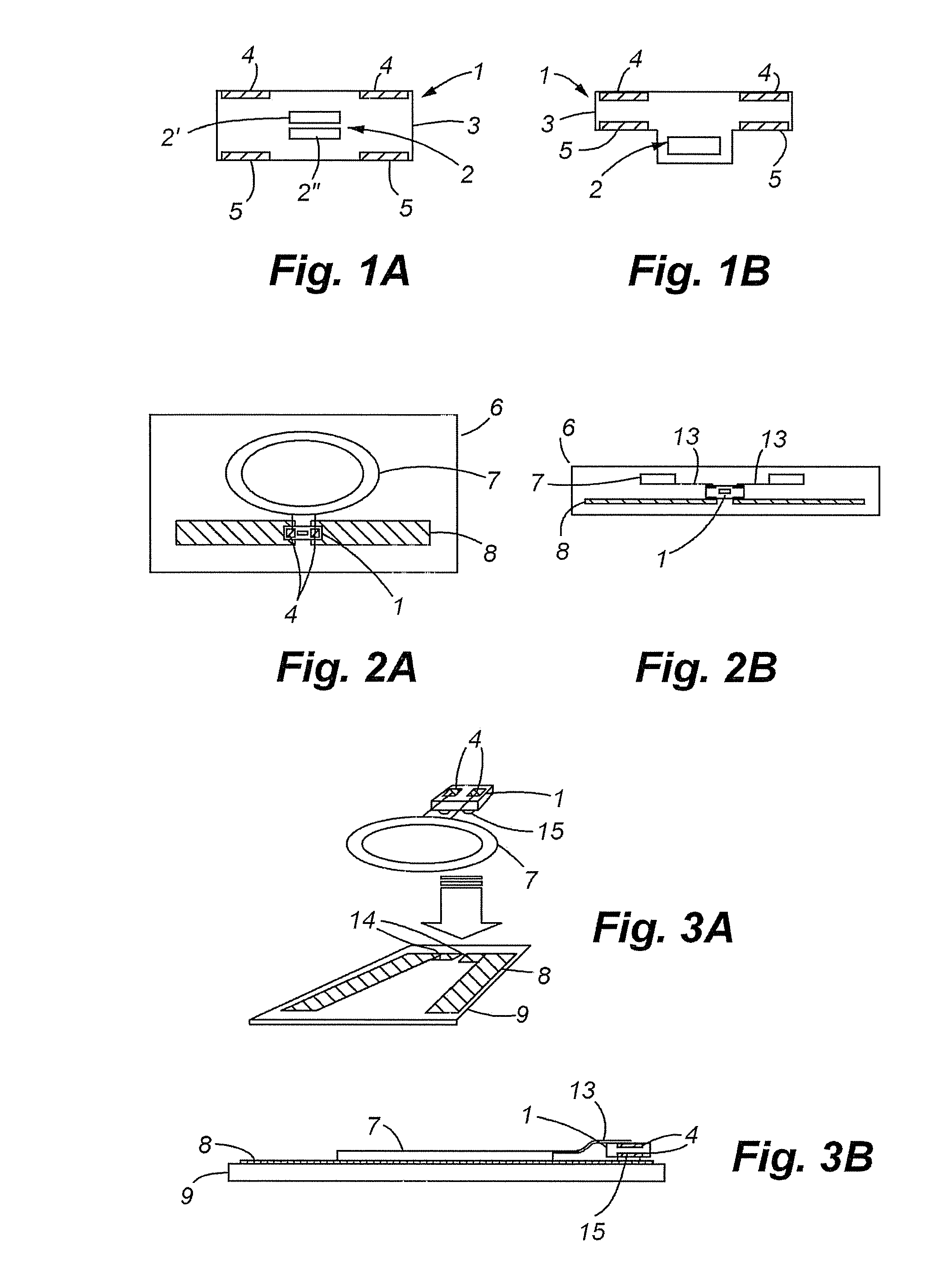
[0021] In accordance with at least one embodiment of the present invention, a chip module being connectable to at least two different antennas by at least two pairs of conductive contact zones is provided. Each pair of contact zones, all being connected to the chip or to chips present in the module, is placed on one side of the module. Since the connections of the two antennas to the module are geometrically clearly separated, the risk of short-circuits are lower. Transponder units being produced with such a module are more reliable and efficient. Additionally, different cost saving methods of manufacture of a contactless transponder unit with two antennas are possible.

Problems solved by technology

But since the demand on the market for hybrid frequency contactless transponder units has remained marginal for a long time, this kind of product never reached mass production volumes.
In fact, this transponder is not able to operate in several frequencies at the same time.
None of these documents show details of how such transponders have to be structured to be suited for mass production processes.

Method used


Image

  • Hybrid frequency contactless transponder unit, module for and method of manufacturing
  • Hybrid frequency contactless transponder unit, module for and method of manufacturing
  • Hybrid frequency contactless transponder unit, module for and method of manufacturing

Examples


Embodiment Construction

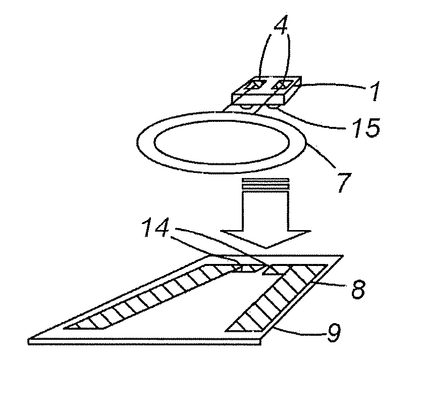
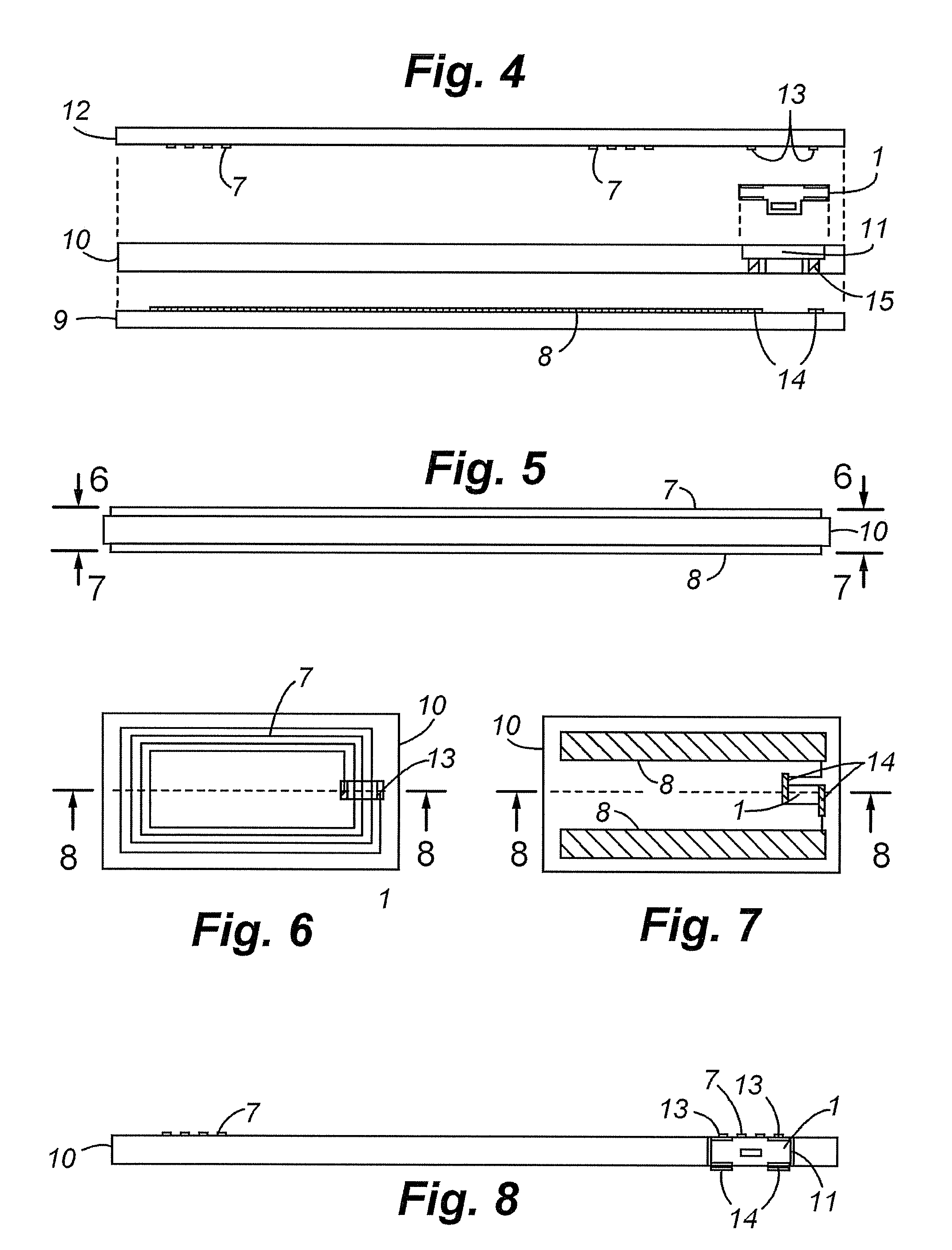
[0034] In FIGS. 1A and 1B, two different embodiments of a chip module 1 of the invention are represented. As with all transponder chip modules, they contain at least a transponder chip 2 or two transponder chips 2′ and 2″ embedded in an insulating housing 3, the chip module being connected (not shown) to external conductive contact zones 4 and 5 at the surface of the housing. There are, in fact, two pairs 4 and 5 of contact zones, each positioned on one of the upper and lower surface of the chip module 1. The housing 3 can have many shapes, for example a square with two well defined upper and lower surface as in FIG. 1A, or also T-shaped as in FIG. 1B, in which the lower surface shows different levels. The contact zones 4 and 5 can be placed anywhere on these surfaces, such that each pair is placed on an opposite side of the chip module 1. A symmetrical position of the contact zones as in FIGS. 1A and 1B may be beneficial, but is not required. The internal structures of the chip mod...


PUM


Abstract

A contactless transponder unit is provided which comprises a chip module, a first antenna connected to two upper conductive contact zones of the chip module and a second antenna connected to two lower conductive contact zones of the chip module. The chip is configured in such a way as to operate the first antenna at a first frequency range and the second antenna at a second frequency range, the first frequency range being different than the second frequency range.

Description

FIELD OF THE INVENTION [0001] The invention relates to a module for a contactless transponder unit, a contactless transponder unit with such a module and methods of manufacturing such contactless transponder unit. In particular, the invention concerns hybrid frequency contactless transponder units. As used herein, “hybrid” is understood to refer to contactless transponder units having two different antennas operating in two different frequency ranges. Contactless smart cards are one of the particular embodiments of the invention. STATE OF THE ART [0002] The different transmission frequencies of transponders are classified into three basic ranges: [0003] Low Frequency (LF): 30-300 kHz [0004] High Frequency (HF): 3-30 MHz (also called Radio Frequency (RF)) [0005] Ultra High Frequency (UHF): 300 MHz-3 GHz (also including Microwave (>3 GHz)) [0006] LF and HF antennas are typically loop antennas (made of wire or band), whereas UHF antennas have more varied forms (dipole, patch, slot a...

Claims


Application Information

Patent Timeline
Patent Type & Authority Applications(United States)
IPC IPC(8): G08B13/14
CPCG06K19/0723G06K19/07767G06K19/07749
Inventor AYALA, STEPHANECURTY, JARI-PASCAL
Owner ASSA ABLOY AB
Learn More