System for joining building boards

a technology of building boards and joints, applied in resiliently-mounted floors, walls, transportation and packaging, etc., can solve the problems of inability to thin floors, manufacturing costs, inconvenience, etc., and achieve the effect of small overall thickness

Inactive Publication Date: 2006-12-26
VALINGE ALUMINUM AB
View PDF24 Cites 23 Cited by
  • Summary
  • Abstract
  • Description
  • Claims
  • Application Information

AI Technical Summary

Benefits of technology

[0021]A main object of the invention therefore is to provide a system for joining together building panels, especially floor panels for hard, floating floors, which allows using floor panels of a smaller overall thickness than present-day floor panels.

Problems solved by technology

These known laminated floors using glued tongue-and-groove joints however suffer from several inconveniences.
First, the requirement of an overall thickness of at least about 7 mm entails an undesirable restraint in connection with the laying of the floor, since it is easier to cope with low thresholds when using thin floor panels, and doors must often be adjusted in height to come clear of the floor laid.
Moreover, manufacturing costs are directly linked with the consumption of material.
Therefore, it is not possible to make the floors thinner using so-called compact laminate, because of the absence of suitable gluing methods for such non-moisture-absorbent core materials.
Third, since the laminate layer of the laminated floors is highly wear-resistant, tool wear is a major problem when working the surface in connection with the formation of the tongue.
Fourth, the strength of the joint, based on a glued tongue-and-groove connection, is restricted by the properties of the core and of the glue as well as by the depth and height of the groove.
Fifth, laying a floor with glued tongue-and-groove joints is time-consuming, in that glue must be applied to every panel on both the long and short sides thereof.
Sixth, it is not possible to disassemble a glued floor once laid, without having to break up the joints.
This is a drawback particularly in rental houses where the flat concerned must be put back into the initial state of occupancy.
Seventh, known laminated floors are not suited for such use as involves a considerable risk of moisture penetrating down into the moisture-sensitive core.
The placement of the underlay is a complicated operation, since the underlay must be placed in edge-to-edge fashion.
It is however not possible simply to use the known joining technique with glued tongues and grooves for very thin floors, e.g. with floor thicknesses of about 3 mm, since a joint based on a tongue-and-groove connection would not be sufficiently strong and practically impossible to produce for such thin floors.
Nor are any other known joining techniques usable for such thin floors.
Another reason why the making of thin floors from e.g. compact laminate involves problems is the thickness tolerances of the panels, being about 0.2-0.3 mm for a panel thickness of about 3 mm.
A 3-mm compact laminate panel having such a thickness tolerance would have, if ground to uniform thickness on its rear side, an unsymmetrical design, entailing the risk of bulging.
Moreover, if the panels have different thicknesses, this also means that the joint will be subjected to excessive load.
Nor is it possible to overcome the above-mentioned problems by using double-adhesive tape or the like on the undersides of the panels, since such a connection catches directly and does not allow for subsequent adjustment of the panels as is The case with ordinary gluing.
Especially, biased clips of this type cannot be used for joining panels of such a small thickness as 3 mm.
Normally, it is not possible to disassemble the floor panels without having access to their undersides.
This known technology relying on clips suffers from the additional drawbacks:Subsequent adjustment of the panels in their longitudinal direction is a complicated operation in connection with laying, since the clips urge the panels tightly against each other.Floor laying using clips is time-consuming.This technique is usable only in those cases where the floor panels are resting on underlying joists with the clips placed therebetween.

Method used


Image

  • System for joining building boards
  • System for joining building boards
  • System for joining building boards

Examples


Embodiment Construction

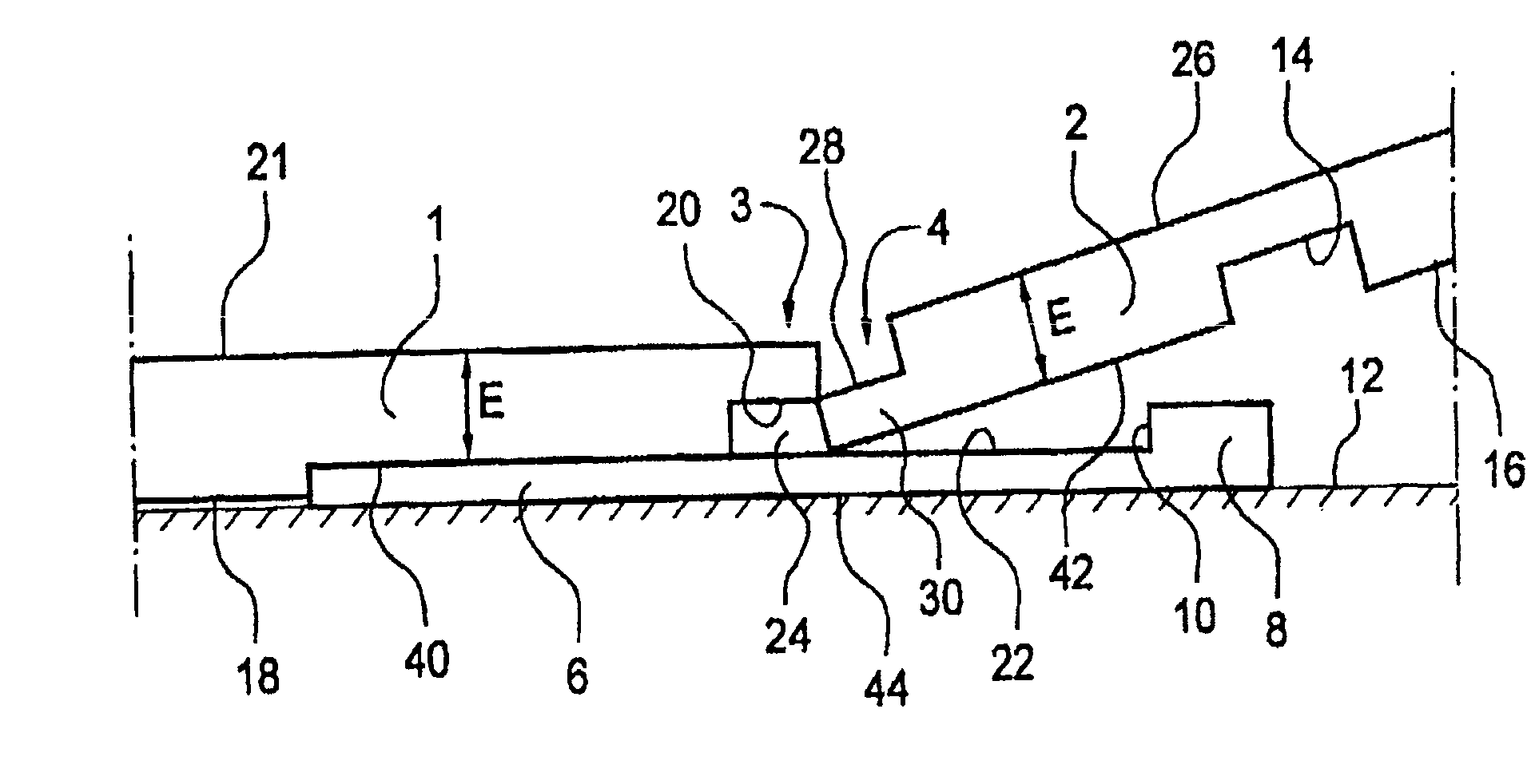
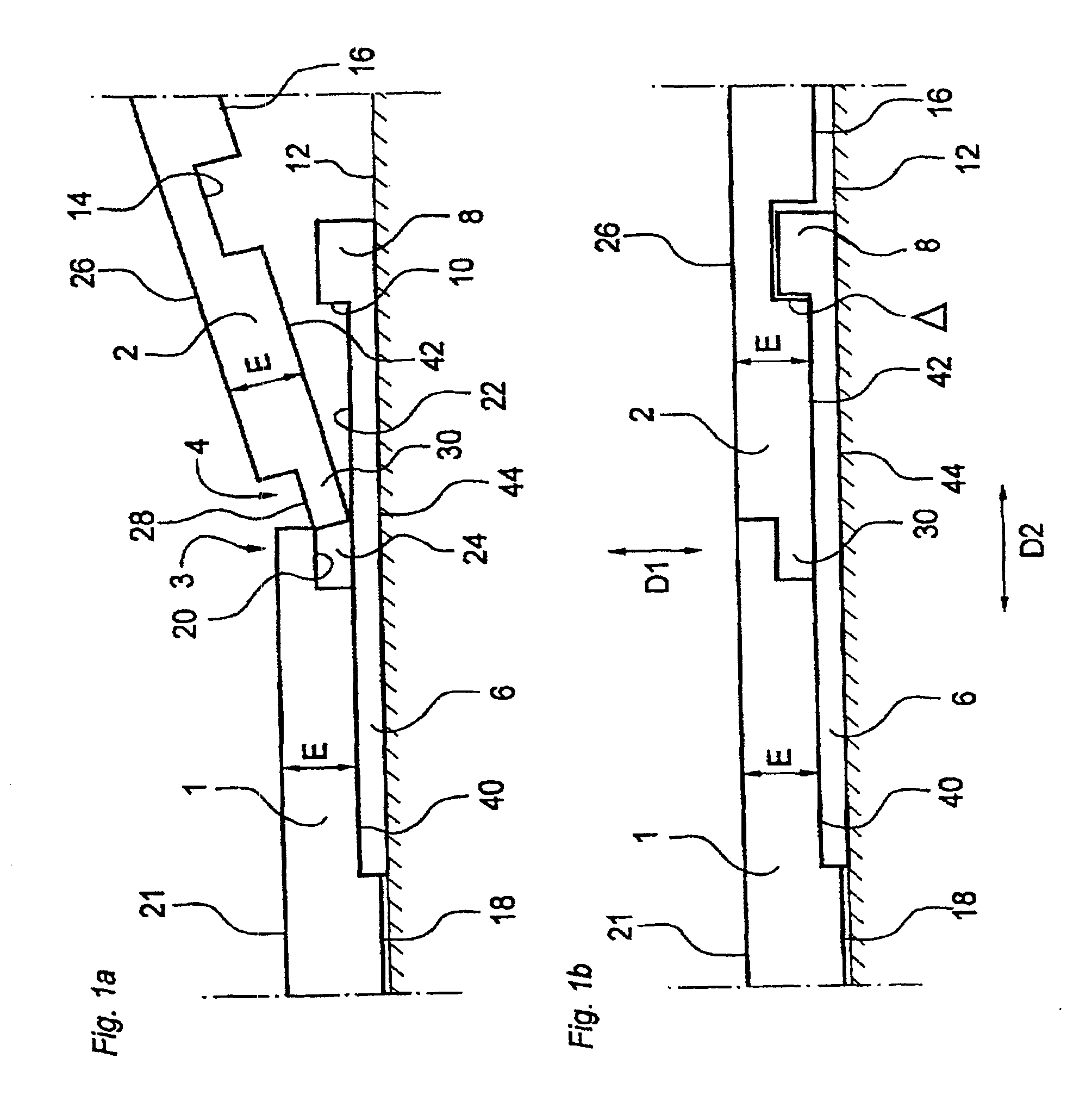
[0062]FIGS. 1a and 1b, to which reference is now made, illustrate a first floor panel 1, hereinafter termed strip panel, and a second floor panel 2, hereinafter termed groove panel. The terms “strip panel” and “groove panel” are merely intended to facilitate the description of the invention, the panels 1, 2 normally being identical in practice. The panels 1 and 2 may be made from compact laminate and may have a thickness of about 3 mm with a thickness tolerance of about ±0.2 mm. Considering this thickness tolerance, the panels 1, 2 are illustrated with different Thicknesses (FIG. 1b), the strip panel 1 having a maximum thickness (3.2 mm) and the groove panel 2 having a minimum thickness (2.8 mm).

[0063]To enable mechanical joining of the panels 1, 2 at opposing joint edges, generally designated 3 and 4, respectively, the panels are provided with grooves and strips as described in the following.

[0064]Reference is now made primarily to FIGS. 1a and 1b, and secondly to FIGS. 4a and 4b s...


PUM


Abstract

The invention relates to a system for laying and mechanically joining building panels, especially thin, hard, floating floors. Adjacent joint edges (3, 4) of two panels (1, 2) engage each other to provide a first mechanical connection locking the joint edges (3, 4) in a first direction (D1) perpendicular to the principal plane of the panels. In each joint, there is further provided a strip (6) which is integrated with one joint edge (3) and which projects behind the other joint edge (4). The strip (6) has an upwardly protruding locking element (8) engaging in a locking groove (14) in the rear side (16) of the other joint edge (4) to form a second mechanical connection locking the panels (1, 2) in a second direction (D2) parallel to the principal plane of the panels and at right angles to the joint. Both the first and the second mechanical connections allow mutual displacement of joined panels (1, 2) in the direction of the joint.

Description

TECHNICAL FIELD[0001]The invention generally relates to a system for providing a joint along adjacent joint edges of two building panels, especially floor panels.[0002]More specifically, the joint is of the type where the adjacent joint edges together form a first mechanical connection locking the joint edges to each other in a first direction at right angles to the principal plane of the panels, and where a locking device forms a second mechanical connection locking the panels to each other in a second direction parallel to the principal plane and at right angles to the joint edges, the locking device comprising a locking groove which extends parallel to and spaced from the joint edge of one of the panels, and said locking groove being open at the rear side of this one panel.[0003]The invention is especially well suited for use in joining floor panels, especially thin laminated floors. Thus, the following description of the prior art and of the objects and features of the invention...

Claims


Application Information

Patent Timeline
Patent Type & Authority Patents(United States)
IPC IPC(8): E04F15/22E04D3/362E04B1/38E04B1/68E04B5/00E04C2/00E04C2/30E04FE04F13/08E04F15/00E04F15/02E04F15/04E04F15/14E04F15/18
CPCE04F13/0801E04F15/02E04F15/04Y10T428/167E04F2201/0153E04F2201/042E04F2201/0517E04F2201/0115E04F15/14
Inventor PERVAN, TONY
Owner VALINGE ALUMINUM AB
Why Eureka
Try Eureka