Wind turbine, drive train assembly, wind turbine nacelle system, methods for converting rotational energy and methods for building a nacelle and for re-equipping a wind turbine

a technology for wind turbines and nacelles, which is applied in the direction of wind turbines, motors, wind energy generation, etc., can solve the problems of increasing production costs, requiring additional parts, and requiring additional assembly and maintenance efforts, so as to achieve the effect of reducing production costs and increasing production costs

Inactive Publication Date: 2012-01-26
SIEMENS GAMESA RENEWABLE ENERGY AS
View PDF3 Cites 128 Cited by
  • Summary
  • Abstract
  • Description
  • Claims
  • Application Information

AI Technical Summary

Benefits of technology

[0008]It is an object of the invention to supply a possibility of how to construct and / or re-equip a wind turbine such that the above-mentioned drawbacks of direct drive and indirect drive systems are reduced.
[0011]In other words, a direct driven generator is put in series with a gear box driven generator. This allows to use each of those two generators under optimum conditions at partial load. At the same time, the costs for both the gear box and the two generators can be substantially reduced in comparison with assemblies that use either direct drive or indirect drive systems. This is due to the fact that smaller devices can generally be used than necessary if used alone to cover the full load. As the mass of a direct drive generator is proportional to its square output, a reduction of the output for example by half would mean a reduction of mass to a quarter. Similar calculations also apply for the mass of gear boxes. Therefore, by combining direct drive and indirect drive systems in one wind turbine, a reduction of overall mass can be realized in comparison with at least a direct drive system. Furthermore, this also implies a major reduction in size of the direct drive generator. While direct driven generators according to the state of the art can reach diameters of up to 6 m, the diameter of a smaller direct driven a generator as can be used in the context of the invention will be substantially reduced. This means that the size of the wind turbine, in particular the nacelle, can also be reduced enormously and also that the transport of the components of such wind turbine to a place where the turbine is assembled gets by far easier.
[0027]In a preferred embodiment, the second generator and the gear box are comprised in a common operation unit. This can optionally be enhanced by the operation unit further comprising an azimuth drive. In other words, it is preferred that use is made of a multibrid generator as described above as a second generator. This is of particular use in the context of the invention, because the combination of two generators along the drive train implies that the overall length of the wind turbine from the rotor to the end of the indirect drive generator (facing away from the first, direct drive generator) is increased in comparison with a wind turbine according to the state of the art taken that both generator assemblies have the same nominal power output. Therefore, any reduction of length, as can be realized by a multibrid generator, is more than welcome and thus highly advantageous.
[0028]It is also preferred that the gear box comprises several output drive trains driving in operation the second generator and at least a third generator. The second generator and the third generator, possibly combined with one or several more generators, are then part of a multi-generator assembly as described above and may be housed in a common housing together. The application of such multi-generator assembly in the context of the invention provides for a lighter weight generator assembly and also implies that the overall load is divided into more than just two parts, namely into one large part covered by the direct drive generator and into several even smaller parts covered by the multitude of indirect drive generators. This can lead to an even better output of electrical energy, i.e. it means an optimum conversion of rotational energy into electrical energy.

Problems solved by technology

Direct driven generators are generally much bigger, heavier and thus costlier to produce and assemble.
However, while gear box driven generators are lighter, smaller and thus cheaper they have the disadvantage of necessitating an additional part, i.e. the gear box.
Such gear box requires additional assembly and maintenance efforts and is yet again an expensive component.
In addition, the noise emission of such gear box in comparison with a direct drive generator is also an important factor which needs to be considered.
Still, even with multibrid or multiple-generator assemblies there remains the problem of relatively high assembly and maintenance efforts for indirectly-driven generator systems.

Method used


Image

  • Wind turbine, drive train assembly, wind turbine nacelle system, methods for converting rotational energy and methods for building a nacelle and for re-equipping a wind turbine
  • Wind turbine, drive train assembly, wind turbine nacelle system, methods for converting rotational energy and methods for building a nacelle and for re-equipping a wind turbine
  • Wind turbine, drive train assembly, wind turbine nacelle system, methods for converting rotational energy and methods for building a nacelle and for re-equipping a wind turbine

Examples


Embodiment Construction

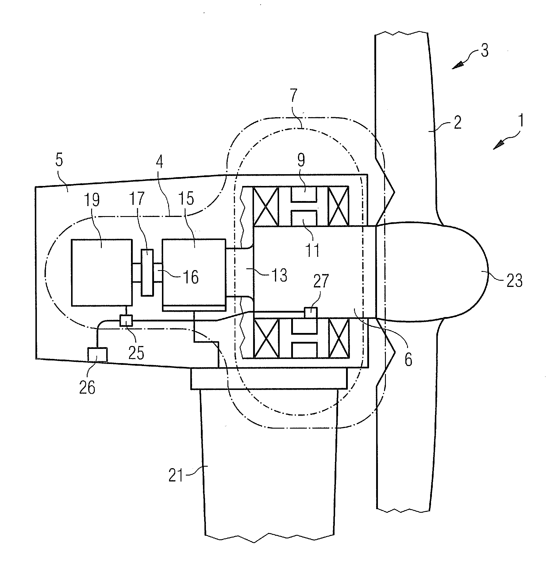
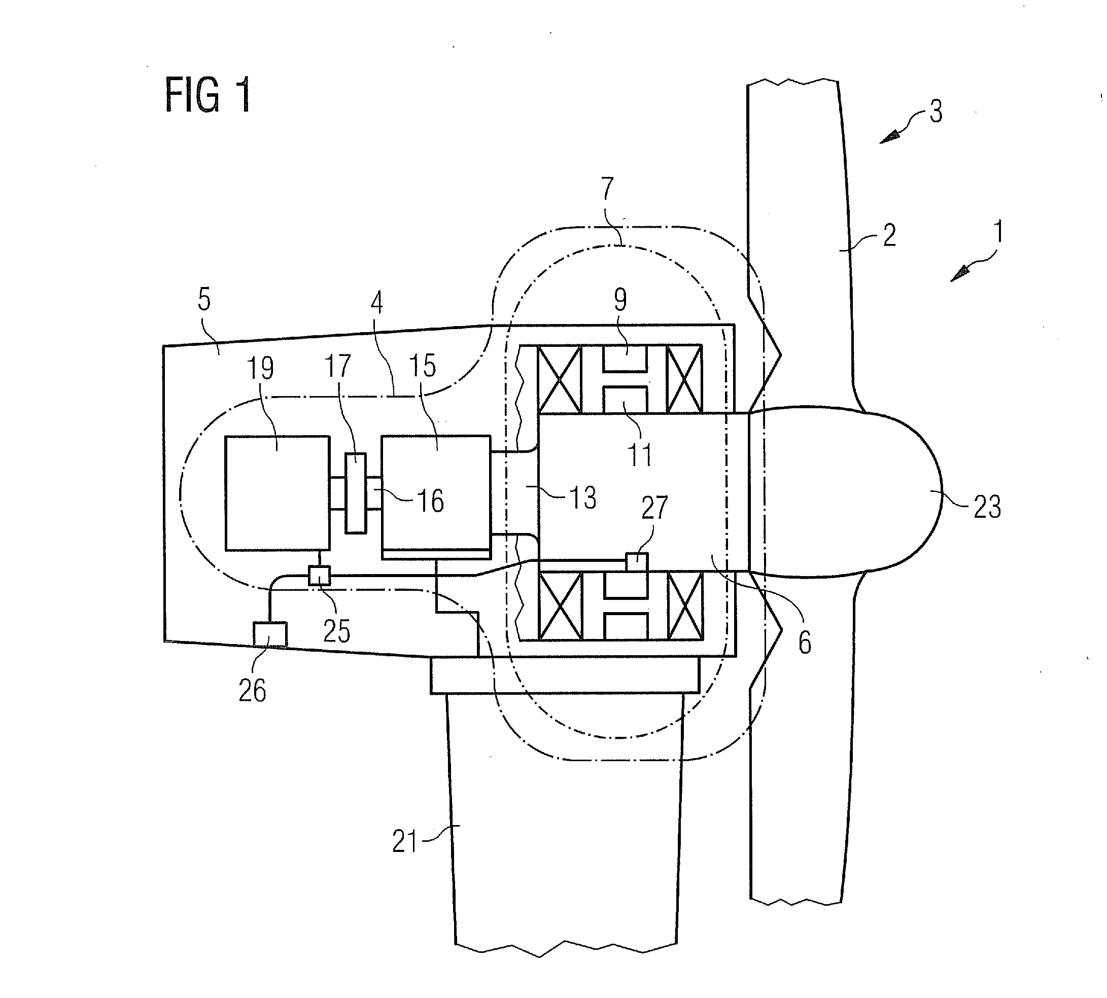
[0037]FIG. 1 shows a sectional view of a wind turbine 1, which is principally made up of tower 21, a nacelle 5 and a drive unit 3, comprising rotor blades 2 connected to a hub 23. The rotational energy of the drive unit 3 is transferred into the inside of the nacelle 5 by means of a drive train 13 with a main shaft 6 coupled to the hub 23. The drive train 13 is part of a drive train assembly 4 further comprising a first generator 7, a gear box 15, an output drive train 16, a break 17 and a second generator 19.

[0038]Furthermore the wind turbine 1 comprises a measurement and adjustment system made up of a measurement unit 26, a control unit 25 and an adjustment unit 27.

[0039]The first generator 7 is realized in the form of a direct drive generator. This means that the first generator 7 comprises a first stator 9 fixedly positioned within a generator housing (not shown) and a first rotor 11 which is directly connected to the drive train 13. Such direct connection means that whenever th...


PUM


Abstract

A wind turbine with a drive train connecting a drive unit with a generator assembly is provided. The generator assembly includes a first generator with a first stator and a first rotor, the first rotor being directly connected to the drive train, and at least a second generator indirectly coupled to the drive train via a gear box. Further, a drive train assembly, a wind turbine nacelle system, a method for converting rotational energy into electrical energy, a method of building a nacelle and methods of re-equipping a wind turbine are provided.

Description

CROSS REFERENCE TO RELATED APPLICATIONS[0001]This application claims priority of European Patent Office Application No. 10169066.1 EP filed Jul. 9, 2010, which is incorporated by reference herein in its entirety.FIELD OF INVENTION[0002]The present invention concerns a wind turbine with a drive train connecting a drive unit (also called rotor unit) with a generator assembly. It also concerns a drive train assembly, a wind turbine nacelle system, a method for converting rotational energy into electrical energy, a method of building a nacelle and methods of re-equipping a wind turbine.BACKGROUND OF INVENTION[0003]Large wind turbine systems for offshore or onshore use convert rotational energy of a rotor driven by the wind into electrical energy. The conversion is either done directly or indirectly. In the first case the relatively slow rotation of a drive train connected to the hub of the wind turbine is directly converted into electrical energy. This is realized by directly attaching ...

Claims


Application Information

Patent Timeline
Patent Type & Authority Applications(United States)
IPC IPC(8): H02P9/06F03D9/00
CPCF03D7/02F03D9/002F03D11/02Y02E10/725Y02B10/30Y02E10/722Y02E10/723F05B2240/40F03D9/25F03D15/00F03D15/10F03D80/88Y02E10/72
Inventor HEDE, IVAN ARTHURHOHLE, ANDREAS CHRISTIANHOHMANN, CHRISTIANKUMMER, CLAUDIAKOLPIN, HELMUTLI, YINGTCHEMTCHOUA, BRICE
Owner SIEMENS GAMESA RENEWABLE ENERGY AS
Why Eureka
Try Eureka