High brightness optical device

a high-brightness, optical device technology, applied in the direction of static indicating devices, lighting and heating apparatus, instruments, etc., can solve the problems of inconvenient installation, unsafe use, and limiting factors of the quality of the display within the end-user's device, etc., to facilitate design and fabrication, high-bright display sources, and high-efficiency use

Active Publication Date: 2012-01-17
LUMUS LTD
View PDF5 Cites 134 Cited by
  • Summary
  • Abstract
  • Description
  • Claims
  • Application Information

AI Technical Summary

Benefits of technology

[0005]The present invention facilitates the design and fabrication of very high brightness display sources for, amongst other applications, head-mounted displays. The invention allows a highly efficient use of the available light of the illumination source, that is to say, a relatively high brightness system, together with relatively low power consumption, can be achieved. The optical system of the present invention is particularly advantageous because it is substantially brighter than state-of-the-art implementations and yet it can be readily incorporated, even into optical systems having specialized configurations.
[0007]An important application of the present invention relates to its implementation in a compact HUD, which alleviates the aforementioned drawbacks. In the HUD design of the present invention, the combiner is illuminated with a compact display source having high brightness and small power consumption. Hence, the overall system is very compact and can be readily installed in a variety of configurations for a wide range of applications.
[0008]A further application of the present invention is the provision of a compact display with a wide FOV for mobile, hand-held application such as cellular phones. In today's wireless internet-access market, sufficient bandwidth is available for full video transmission. The limiting factor remains the quality of the display within the end-user's device. The mobility requirement restricts the physical size of the displays, and the result is a direct-display with a poor image viewing quality. The present invention enables a physically very compact display with a very large and bright virtual image. This is a key feature in mobile communications, and especially for mobile Internet access, solving one of the main limitations for its practical implementation. Hence, the present invention enables the viewing of the digital content of a full format Internet page within a small, hand-held device, such as a cellular phone.
[0010]For all possible applications, the present invention is particularly advantageous for substrate-mode configuration, that is, for a configuration comprising a light-transmitting substrate having at least two major surfaces and edges; optical means for coupling the light from the imaging module into said substrate by total internal reflection, and at least one partially reflecting surface located in said substrate for coupling the light onto the viewer's eye. The combination of the present invention with a substrate-mode configuration can yield a very compact and convenient optical system along with very high brightness and low power consumption.
[0011]The broad object of the present invention is therefore to alleviate the drawbacks of state-of-the-art virtual image display devices and to provide other optical components and systems having improved performance, according to specific requirements.

Problems solved by technology

Nevertheless, state-of-the-art HUDs suffer several significant drawbacks.
As a result, the present HUD systems usually require complicated high brightness display sources which are necessarily bulky, and large, and require a considerable installation space, which makes it inconvenient for installation and at times even unsafe to use.
The limiting factor remains the quality of the display within the end-user's device.
The mobility requirement restricts the physical size of the displays, and the result is a direct-display with a poor image viewing quality.

Method used


Image

  • High brightness optical device
  • High brightness optical device
  • High brightness optical device

Examples


Embodiment Construction

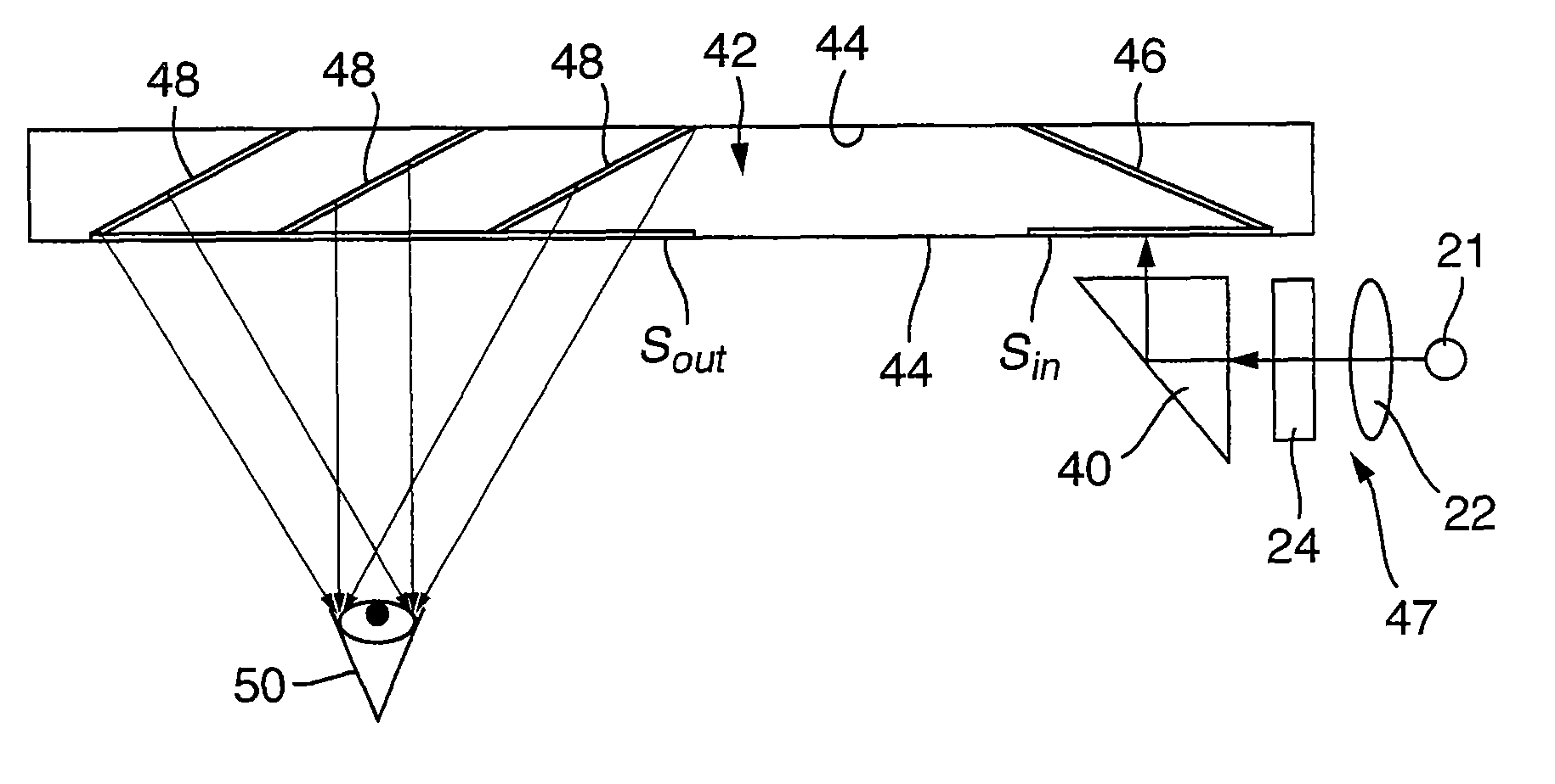
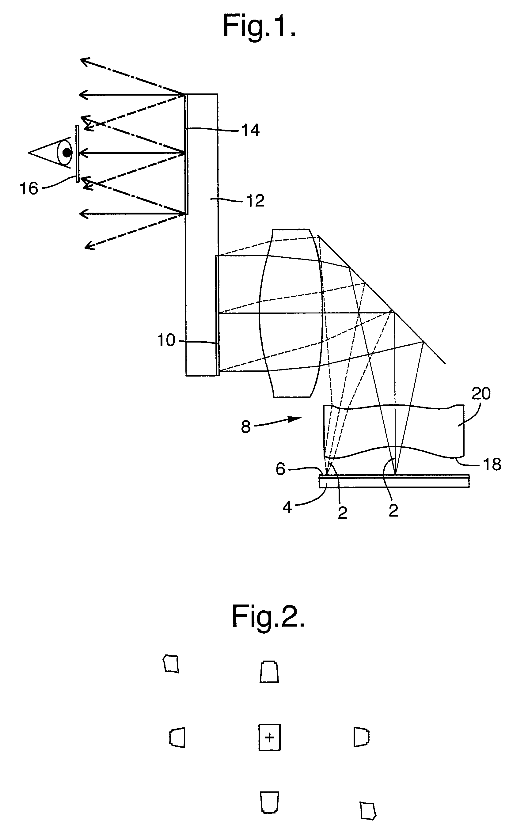
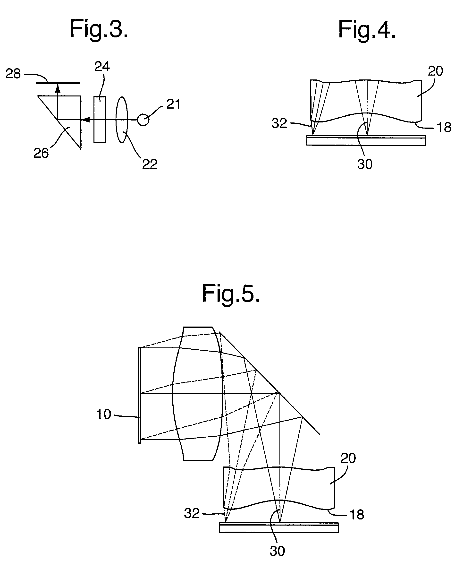
[0027]FIG. 1 illustrates a conventional virtual-image display optics arrangement, wherein light waves 2 emerging from a display source 4 are diffused by a light diffusing mechanism 6, that can be an integral part of the display source, such that each light wave which is emerging from a single point of the display source is diverged into a finite solid angle, e.g., a cone. The light waves are then imaged by an imaging module 8 and illuminate the input aperture 10 of a projection module 12. The light waves are directed to a surface area of the output aperture 14 of the projection module and then coupled into the exit pupil 16 of the optical system. For most optical systems this exit pupil 16 can be defined as the head-motion-box (HMB) or the eye-motion-box (EMB) for a biocular or a monocular respectively, that is, the place where the viewer can see the entire image simultaneously. In addition, for see-through optical systems, where the image is projected into the viewer's eye(s) throu...


PUM


Abstract

There is provided an optical device, composed of a display source (4), an imaging optical module (8), a projection module (12) having a projection mechanism including an input aperture (10) and output aperture (14) defined by a surface area, and an exit pupil (16). The projection mechanism is non-uniform over the area of the output aperture (14).

Description

FIELD OF THE INVENTION[0001]The present invention relates to display systems, and more particularly to see-through display systems.[0002]The invention can be implemented to advantage in a large number of personal imaging applications, such as, head-mounted and head-up displays, hand-held displays, as well as binoculars, monoculars and bioculars. In addition, such systems may serve as image projection systems for front projectors utilizable in conference rooms and as rear projection TV screens.BACKGROUND OF THE INVENTION[0003]One of the important applications for compact optical elements is in head-mounted displays (HMDs) wherein an optical module serves both as an imaging lens and a combiner, in which a two-dimensional display is imaged to infinity and reflected into the eye of an observer. The image to be displayed is obtained directly from either a spatial light modulator (SLM), such as a cathode ray tube (CRT), a liquid crystal display (LCD), an organic light emitting diode array...

Claims


Application Information

Patent Timeline
Patent Type & Authority Patents(United States)
IPC IPC(8): G02B27/14G09G5/00F21V7/04G02B6/00G02B27/00G02B27/01
CPCG02B13/22G02B27/0081G02B27/0172G02B2027/0118G02B2027/0174
Inventor AMITAI, YAAKOVGELBERG, JONATHAN
Owner LUMUS LTD
Why Eureka
Try Eureka