Loading Ramp and Door for a Storage Vehcile

a technology for loading ramps and storage vehicles, which is applied in the directions of loading/unloading vehicle arrangment, transportation and packaging, transportation items, etc., can solve the problems of poor door, rolling equipment to scrape the ramp or the vehicle floor, and the conventional ramp is not particularly well-adapted

Active Publication Date: 2012-08-23
BASS ANTHONY C +1
View PDF11 Cites 2 Cited by
  • Summary
  • Abstract
  • Description
  • Claims
  • Application Information

AI Technical Summary

Benefits of technology

[0008]Briefly described, an object of the present invention is to provide a rear door that also serves as a loading ramp, combined with an interior dovetail placed inside the storage body of the truck to assist with loading equipment.

Problems solved by technology

Unfortunately, conventional ramps are not particularly well-adapted for enabling multi-axle items such as power equipment, loading carts, and the like to board and exit the storage area of the vehicle.
Many such ramps are made of expanded metal, which is not strong enough to support heavier equipment and is a very poor door if the equipment is intended to be stored full time.
Other ramps use solid steel, but since a solid steel ramp is often too heavy for one person to operate, the ramp is split into two pieces that are raised and lowered separately.
In addition, conventional ramps are typically shaped undesirably and may cause rolling equipment to scrape the ramp or vehicle floor due to the acute angle that the ramp connects with the floor of the storage area.
There is a problem with the typical location of these dovetails, however.
If the dovetail is built outside of the truck storage area, the ramp then hangs off the dovetail and cannot be used as the door of the truck.
If the dovetail is built inside the truck storage area, then it typically takes up too much space and dramatically reduces the storage area inside the truck.
Other designs have attempted to build the ramp long enough that the connection between the ramp and the floor creates a gentler angle for the equipment, however, such ramps may be too long to be useful as the door of the storage area unless the ramp is foldable in some way.

Method used


Image

  • Loading Ramp and Door for a Storage Vehcile
  • Loading Ramp and Door for a Storage Vehcile
  • Loading Ramp and Door for a Storage Vehcile

Examples


Embodiment Construction

[0024]In describing preferred embodiments of the present invention illustrated in the Figures, specific terminology is employed for the sake of clarity. The invention, however, is not intended to be limited to the specific terminology so selected, and it is to be understood that each specific element includes all technical equivalents that operate in a similar manner to accomplish a similar purpose.

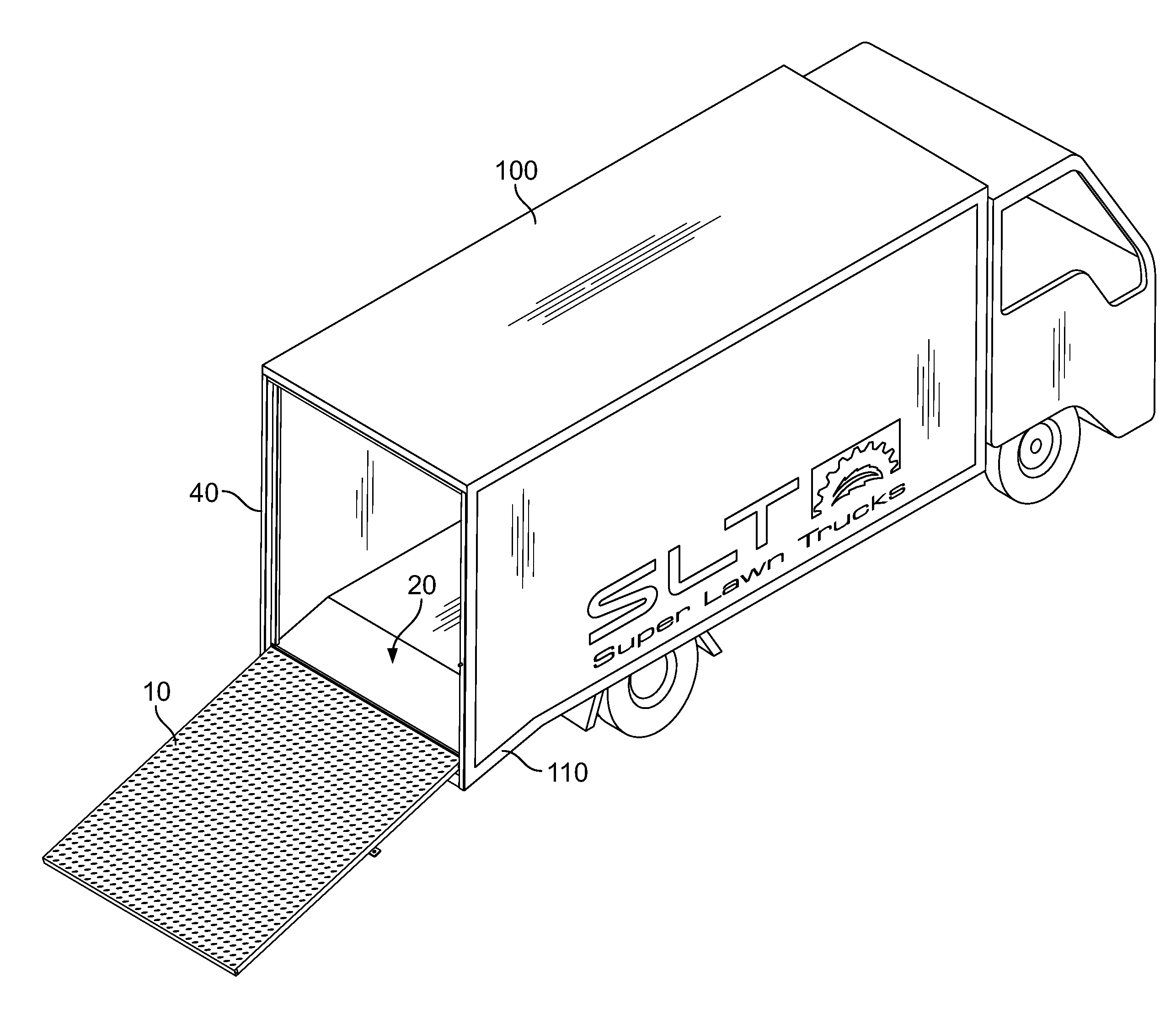
[0025]In accordance with the present invention, a storage vehicle, such as a fully enclosed storage truck, covered van body, and the like, is provided that includes an angled extension built into the storage area, a dovetail structure as part of the extension, and a substantially weather tight door enclosing the storage area of the vehicle. By “substantially weather tight” it is meant that the openings between the door and frame may be small enough to protect the contents of the truck from weather events, such as rain or snow. The door is typically not considered “air tight” or “water tig...


PUM


Abstract

A loading ramp for a vehicle having a storage area is disclosed, wherein the loading ramp may also serve as a substantially weather tight door for the storage area. The loading ramp comprises a frame structure attached to the vehicle by angled extension members that allow the bottom of the frame to extend below the floor of the storage area. The loading ramp is pivotally attached to the frame. A dovetail structure is built onto the angled extension members, the dovetail being angled to match the angle of the ramp. A hydraulic cylinder and automatic control system is also provided to assist in raising and lowering the ramp.

Description

PRIORITY CLAIM TO RELATED APPLICATIONS[0001]The present United States non-provisional patent application is related to, and hereby claims priority to, and the full benefit of the filing date of provisional patent application Ser. No. 61 / 405,176, filed on Oct. 20, 2010 by the same named inventors, incorporated herein by reference.TECHNICAL FIELD[0002]The present invention relates generally to a combination storage door and loading ramp for a storage vehicle, and, more specifically, to a substantially sealable rear door that converts into a loading ramp for a storage truck or van.BACKGROUND OF THE INVENTION[0003]Ramps attachable to the rear of a truck or similar vehicle are known in the art. For example, see U.S. Pat. Nos. 4,979,867; 5,156,432; 5,678,984; and 6,102,646, the disclosures of which are incorporated herein by reference. Unfortunately, conventional ramps are not particularly well-adapted for enabling multi-axle items such as power equipment, loading carts, and the like to b...

Claims


Application Information

Patent Timeline
Patent Type & Authority Applications(United States)
IPC IPC(8): B60P1/43
CPCB60P1/435
Inventor BASS, ANTHONY C.WRAY, ROBERT H.
Owner BASS ANTHONY C
Why Eureka
Try Eureka