Friction plate and wet-type multi-plate clutch having such friction plate

a multi-plate clutch and friction plate technology, which is applied in the direction of fluid-actuated clutches, clutches, non-mechanical actuated clutches, etc., can solve the problems of increasing the drag torque, and the request for further reducing the drag torque cannot be satisfied, so as to stabilize the quality, reduce the drag torque during idle rotation, and reduce the effect of shock upon the engagemen

Inactive Publication Date: 2007-08-30
NSK WARNER
View PDF32 Cites 39 Cited by
  • Summary
  • Abstract
  • Description
  • Claims
  • Application Information

AI Technical Summary

Benefits of technology

[0012] Accordingly, an object of the present invention is to provide a friction plate in which drag torque during an idle rotation is small and there is no dispersion in a friction property upon engagement thereby to stabilize a quality and shock upon the engagement is small and which has excellent heat-resistance and can reduce the drag torque during the idle rotation considerably in comparison with conventional friction plates, and a wet-type multi-plate clutch having such a friction plate.

Problems solved by technology

However, recently, in order to enhance response of the transmission for the purpose of achieving not only enhanced reduction of fuel consumption but also enhancement of power performance, a clearance between the friction plate and the separator plate has been made smaller than that those in the conventional clutches, with the result that, during an idle rotation, drag torque caused by an oil film existing between the friction plate and the separator plate tends to be increased.
Particularly, in the case where the clearance between the friction plate and the separator plate is small, the difficulty of discharging of the oil becomes noticeable in an area where revolution per minute is small, thereby increasing the drag torque due to viscosity between the friction material and the opposing separator plate.
In the conventional friction plates, since the oil could not discharge adequately from the friction surface, the request for further reducing the drag torque could not be satisfied.
Particularly, in the low rotational speed area, the drag torque could not be reduced.

Method used


Image

  • Friction plate and wet-type multi-plate clutch having such friction plate
  • Friction plate and wet-type multi-plate clutch having such friction plate
  • Friction plate and wet-type multi-plate clutch having such friction plate

Examples


first embodiment

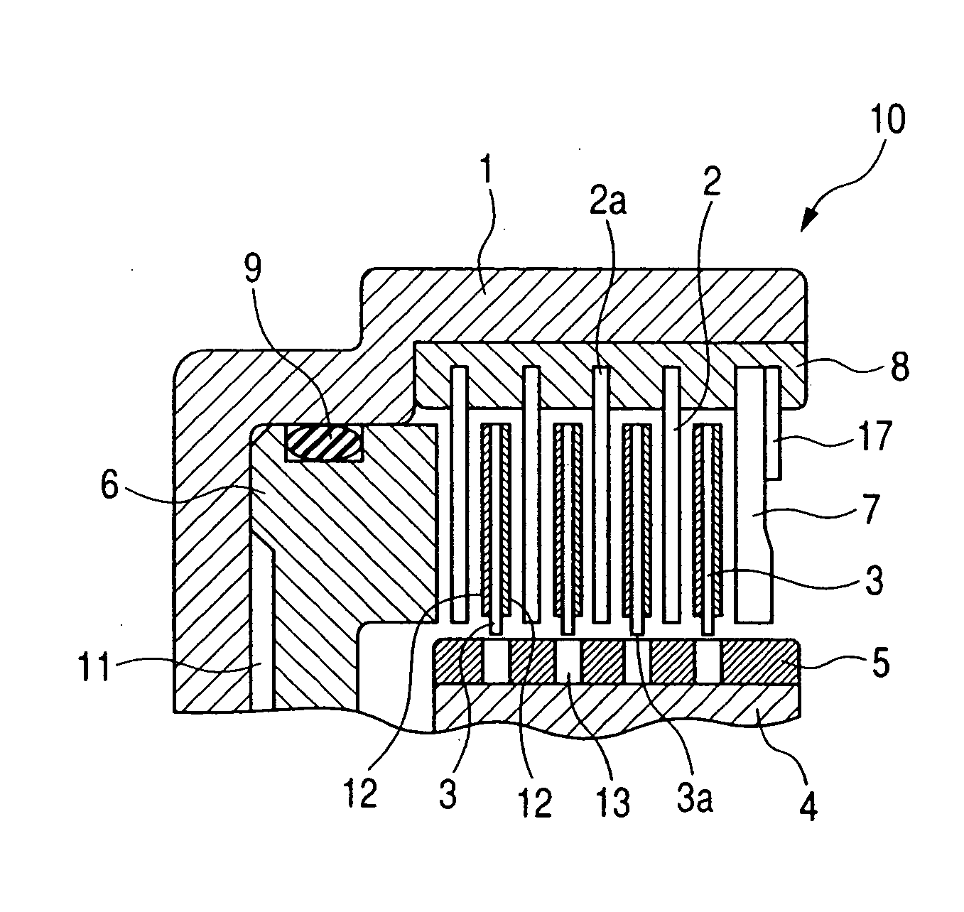
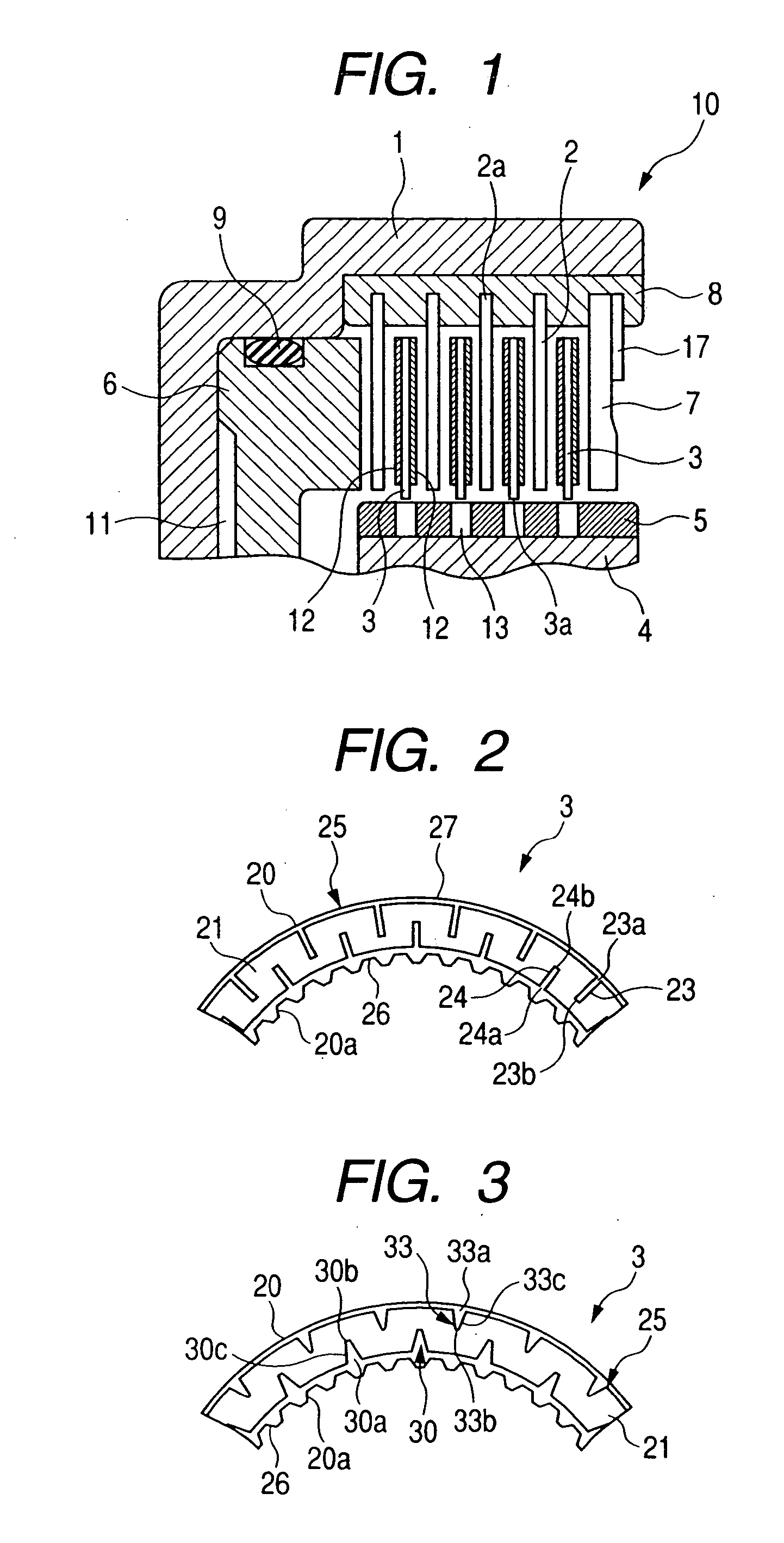
[0036]FIG. 2 is a partial front view of a friction plate 3, showing a first embodiment of the present invention. The friction plate 3 has a friction surface 25 formed by sticking or adhering an annular friction material 21 to a substantially annular core plate 20. The core plate 20 is provided at its inner periphery with splines 20a engaged by the splines 5 of the hub 4.

[0037] As shown, the annular friction material 21 is provided with first oil grooves 24 each having an opening portion 24a opened to an inner peripheral edge 26 of the friction plate 3 and an end portion 24b terminating at a point between the inner peripheral edge and an outer peripheral edge, and second oil grooves 23 each having an opening portion 23a opened to the outer peripheral edge 27 of the friction plate 3 and an end portion 23b terminating at a point between the inner and outer peripheral edges. The first oil grooves 24 and the second oil grooves 23 are alternately arranged along a circumferential directio...

second embodiment

[0040]FIG. 3 is a partial front view of the friction plate 3, showing a second embodiment of the present invention. A fundamental construction of the second embodiment is the same as that of the first embodiment. Accordingly, only differences will be described. This is also true with respect to third, fourth and fifth embodiments which will be described later.

[0041] In the second embodiment, each of first oil grooves 30 each having an opening portion 30a opened to the inner peripheral edge 26 of the friction plate 3 and an end portion 30b terminating at a point between the inner and outer peripheral edges and each of second oil grooves 33 each having an opening portion opened to the outer peripheral edge 27 and an end portion terminating at a point between the inner and outer peripheral edges has a tapered configuration.

[0042] As shown, each first oil groove 30 has tapered portions 30c extending from both circumferential ends of the opening portion 30a to the end portion 30b. Acco...

third embodiment

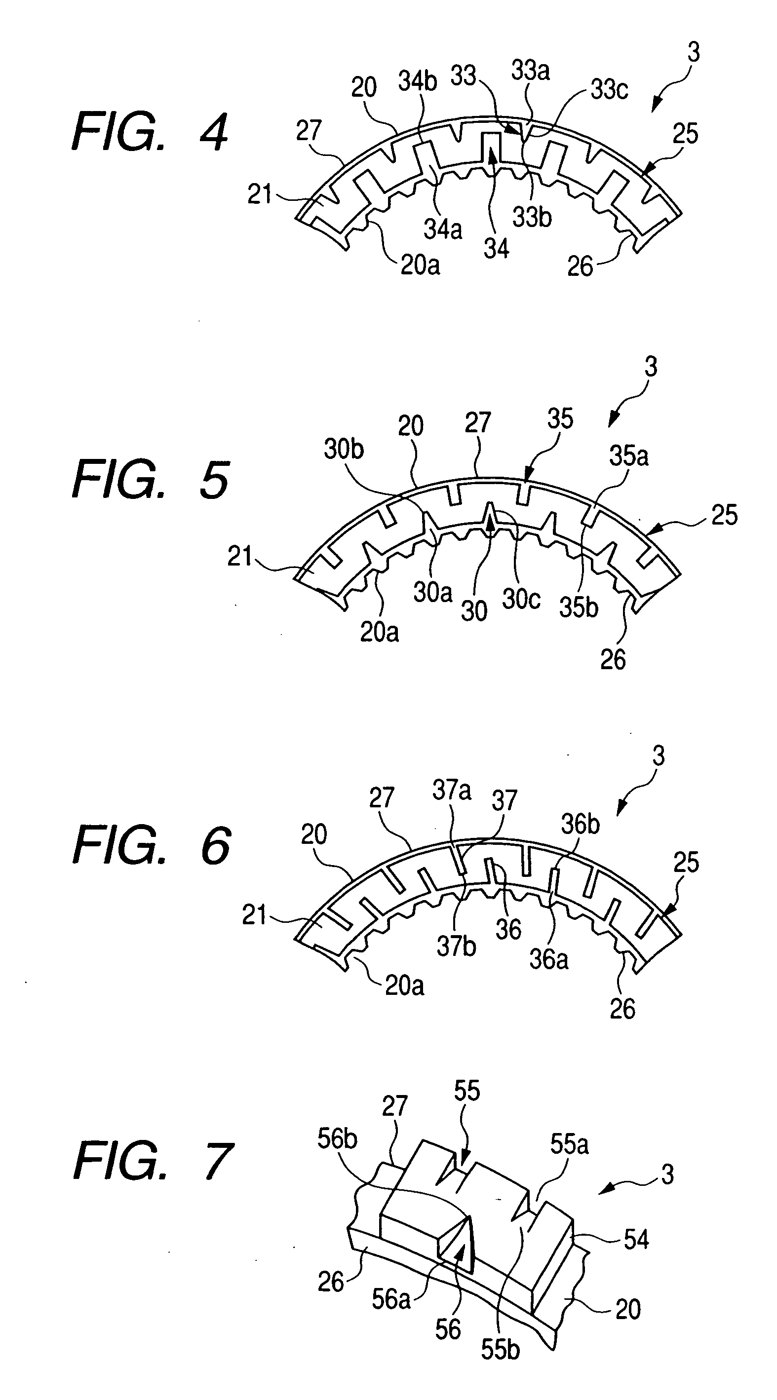
[0045]FIG. 4 is a partial front view of a friction plate 3, showing a third embodiment of the present invention. A fundamental construction of the third embodiment is the same as that of the second embodiment. Accordingly, only a difference will be described.

[0046] The third embodiment is an alteration of the second embodiment. In this third embodiment, a configuration of a first oil groove differs from that of the second embodiment. A first oil groove 34 has generally a rectangular configuration and includes an opening portion 34a opened to the inner peripheral edge 26 of the friction plate 3 and an end portion 34b terminating at a point between the inner and outer peripheral edges, and a circumferential width of the opening portion 34a is substantially the same as that of the end portion 34b. Further, similar to the first embodiment, the first oil grooves 34 and the second oil grooves 33 are alternately arranged along a circumferential direction substantially equidistantly.


PUM


Abstract

The present invention provides a friction plate having a friction surface formed by sticking an annular friction material to a substantially annular core plate and wherein the friction surface is provided with a first oil groove having an opening portion opened to an inner peripheral edge of the friction plate and an end terminating at a point between the inner peripheral edge and an outer peripheral edge, and a second oil groove having an opening portion opened to the outer peripheral edge of the friction plate and an end terminating at a point between the inner peripheral edge.

Description

BACKGROUND OF THE INVENTION [0001] 1. Field of the Invention [0002] The present invention relates to a friction plate used in a clutch and / or a brake of an automatic transmission (AT) of a vehicle and a wet-type multi-plate clutch having such a friction plate. More specifically, the present invention relates to an improvement in an oil passage formed in a friction surface of a friction plate. [0003] 2. Description of the Related Art [0004] In general, in a wet-type multi-plate clutch, friction plates and separator plates are arranged alternately between a drum and a hub of a clutch or a brake, and, engagement and disengagement of the clutch are performed by pressurizing and releasing a clutch piston. [0005] Further, recently, request for reducing fuel consumption in a vehicle has been increased more and more, and thus, also in an automatic transmission, in order to reduce power loss during the disengagement of the clutch, further reduction of drag torque between the friction plate a...

Claims


Application Information

Patent Timeline
Patent Type & Authority Applications(United States)
IPC IPC(8): F16D13/00
CPCF16D13/648F16D2069/004F16D25/0638F16D25/123
Inventor MIYAZAKI, TOMOYUKIKOBAYASHI, MASAHIRO
Owner NSK WARNER
Why Eureka
Try Eureka