AI technical title is built by Patsnap AI team. It summarizes the technical point description of the patent document.
a technology of laser pulse and ion source, which is applied in the direction of particle separator tube details, separation process, and dispersed particle separation, etc., can solve the problems of inefficient ap-maldi, lack of time-sequenced optics with laser pulse limit ion extraction and transmission efficiency, and inefficient atmospheric pressure optics with this device, etc., to achieve efficient extraction and increase the ionization efficiency of a sample
Inactive Publication Date: 2010-10-19
PERKINELMER HEALTH SCIENCES INC +1
View PDF80 Cites 23 Cited by
Summary
Abstract
Description
Claims
Application Information
AI Technical Summary
This helps you quickly interpret patents by identifying the three key elements:
Problems solved by technology
Method used
Benefits of technology
Benefits of technology
[0016]In accordance with the present invention, associated methods of sample charging, laser desorption and sample ionization are intended to improve the collection efficiency and ionization efficiency of atmospheric pressure, intermediate pressure and vacuum laser desorption ionization.
[0017]Two advantages of the current device should be emphasized. First, precisely timing the sequence of laser pulse with ion extraction under high voltage followed by reduction of the electric field in the extraction and focusing region before losing ions to surfaces. The field in the extraction and focusing region is reduced so that the ions are efficiently focused and transmitted through a conductance aperture into a lower pressure region on the path to a mass analyzer. The second important advantage is the ability to populate the sample surface with ions of the sample polarity as the analyte ions to be extracted. This condition drives the equilibrium toward product with an excess of reagent ions compared to conventional MALDI and increases the efficiency of ionization of analyte. One aspect of the current invention is to precharge a sample prior to laser desorption to enhance the yield of ions from a given sample.
[0019]An object of this invention is to use specialized target surfaces with shaped needles or electrodes behind the sample in order to control the electric field experienced by the sample during and after laser pulse. By varying voltage in space and time, optimum sample precharging, ion generation and extraction of ions can be achieved.
[0021]In accordance with the present invention, atmospheric pressure, intermediate pressure and vacuum laser desorption ion sources comprise ionization chambers and transmission devices encompassing targets for holding samples, lasers to illuminate said targets resulting in desorption and ionization of the samples, time-sequenced electrostatic potentials to foster efficient extraction, focusing, and selecting of resulting gas-phase ions. Laser desorption ion sources in accordance with the invention also comprise a means to accumulate charge on a sample prior to laser desorption of the sample and a means to conduct gas phase ionization of laser desorbed neutral sample molecules to increase the ionization efficiency of a sample during and after a desorption laser pulse.
Problems solved by technology
Ironically, the Franzen and Koster patent begins by arguing that AP-MALDI is inefficient and that augmenting ionization efficiency with gas phase ion-molecule reactions or desorbed neutral species with gas phase reagent ions at atmospheric pressure would offset some of the transmission losses that would occur by inefficient transport from atmospheric pressure.
The lack of efficient atmospheric pressure optics with this device requires precise alignment and positioning of sample and the laser beam relative to the vacuum inlet.
The lack of time-sequenced optics with the laser pulse limit ion extraction and transmission efficiency.
In addition, it is envisioned that mirrored reflective surfaces close to the plume of the MALDI target would tend to become contaminated and degraded in their optical performance.
In addition, the sampling of ions from an electric field between the target and aperture into the field-free region of the vacuum inlet tube would cause rim losses from field penetration and degrade the transport efficiency.
The lack of time-sequenced optics with the laser pulse limit ion extraction and transmission efficiency.
This device is still subordinate to alignment of laser, target, and lacks spatial or temporal optics to facilitate efficient ion transmission to the mass analyzer.
The lack of time-sequenced optics with the laser pulse limit ion extraction and transmission efficiency.
Method used
Image
Click on the blue label to locate the original text in one second.
Reading with bidirectional positioning of images and text.
Examples
Embodiment Construction
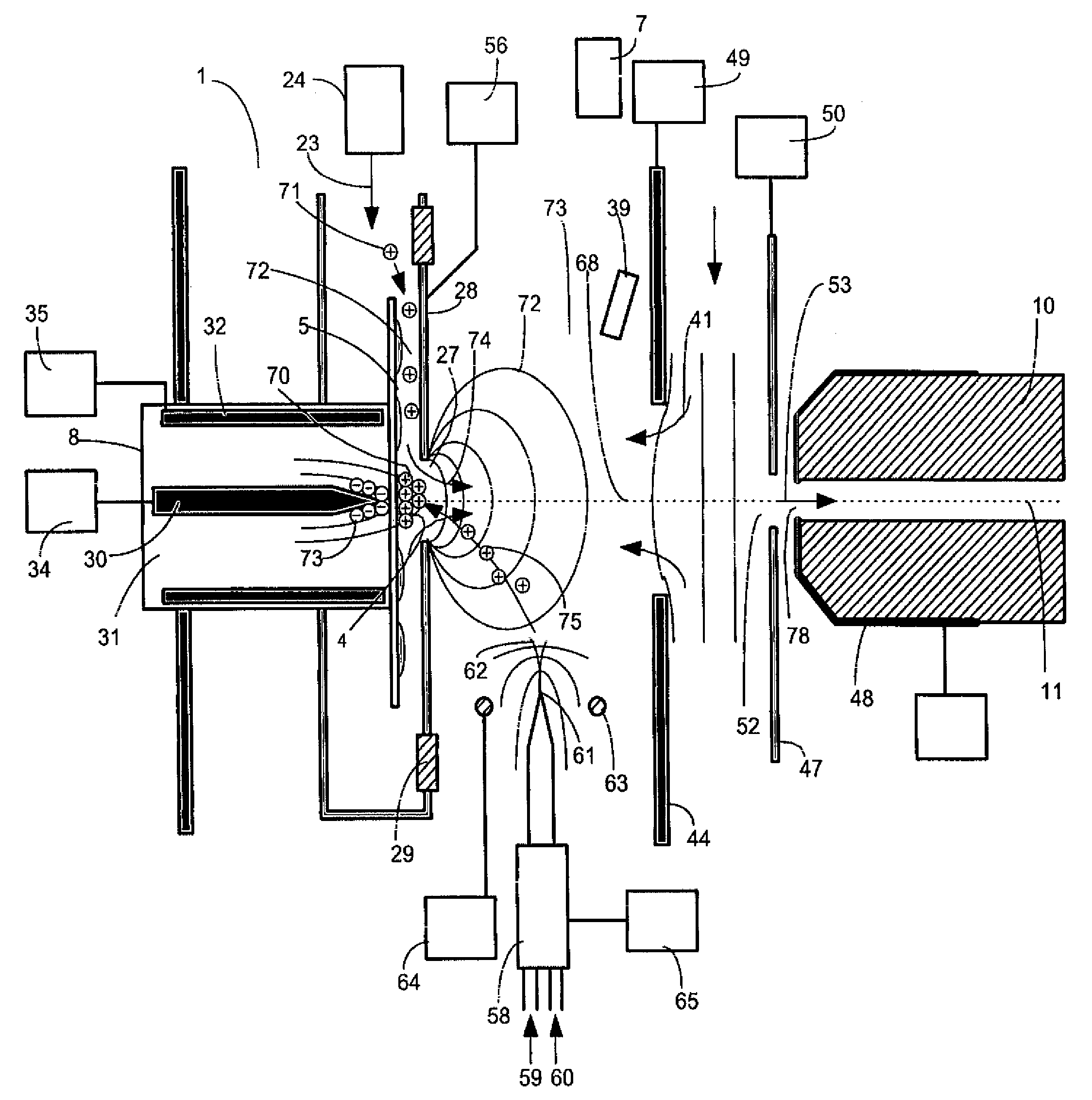
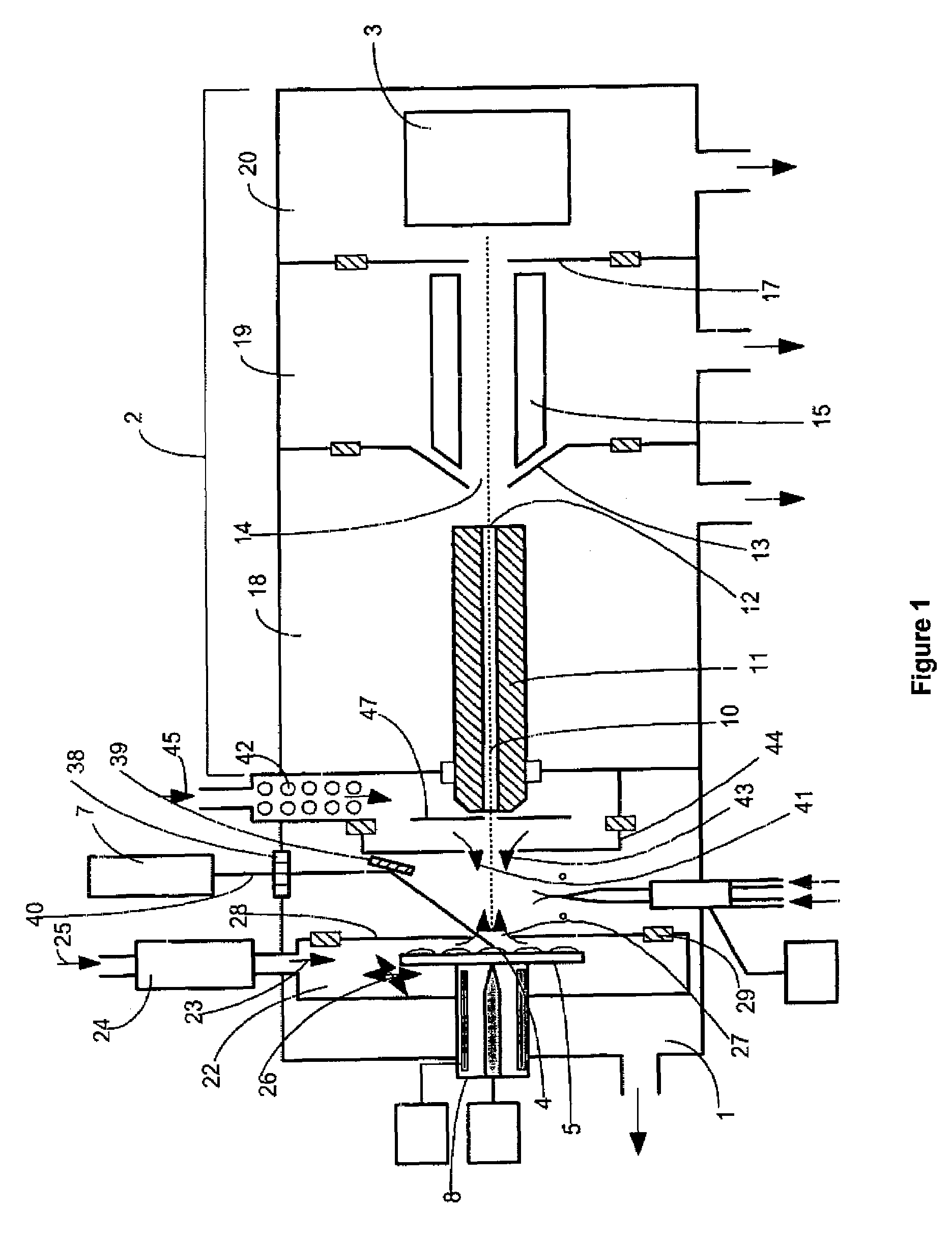
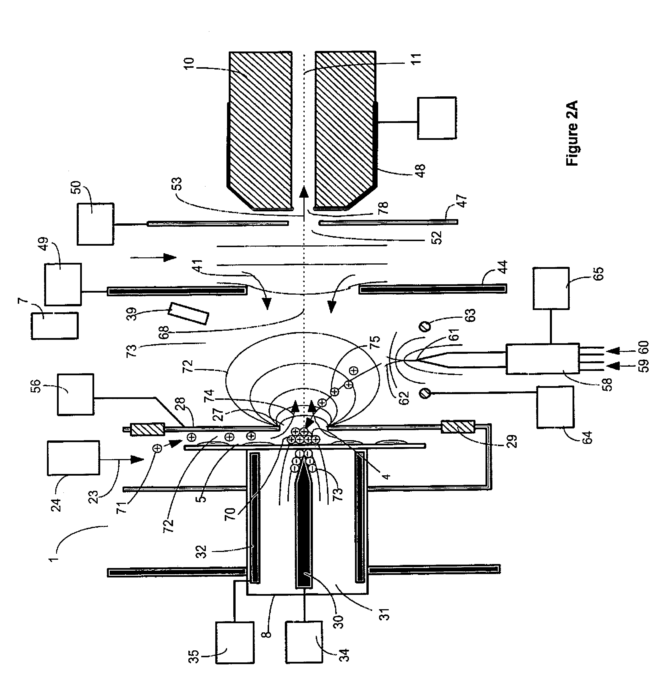
[0048]A preferred embodiment of the invention comprising an atmospheric pressure Laser Desorption Ionization source with sample surface charging is diagrammed in FIG. 1. Operating details for Laser Desorption Ionization source 1 are diagrammed in FIGS. 2A through 2D. Laser Desorption Ionization (LDI) source 1 interfaced to vacuum system 2 comprising ion transfer optics and mass to charge analyzer with detector 3, produces ions from sample 4 on target plate 5. A portion of the laser desorption ion population produced is focused into bore 10 of capillary 11. Ions exit capillary bore 10 at capillary exit end 12 into vacuum and are accelerated in a free jet expansion of neutral background gas flowing through capillary bore 10 from atmospheric pressure ion source 1. Capillary 11 may comprise a dielectric capillary with conductive electrodes on the entrance and exit faces, a heated electrically conductive capillary, a nozzle, an orifice or an array of orifices into vacuum. Ions pass throu...
PUM
Abstract
Atmospheric pressure, intermediate pressure and vacuum laser desorption ionization methods and ion sources are configured to increase ionization efficiency and the efficiency of transmitting ions to a mass to charge analyzer or ion mobility analyzer. An electric field is applied in the region of a sample target to accumulate ions generated from a local ion source on a solid or liquid phase sample prior to applying a laser desorption pulse. The electric field is changed just prior to or during the desorption laser pulse to promote the desorption of charged species and improve the ionization efficiency of desorbed sample species. After a delay, the electric field may be further changed to optimize focusing and transmission of ions into a mass spectrometer or ion mobility analyzer. Charged species may also be added to the region of the laser desorbed sample plume to promote ion-molecule reactions between the added ions and desorbed neutral sample species, increasing desorbed sample ionization efficiency and / or creating desired product ion species. The cycling of electric field changes is repeated in a timed sequence with one or more desorption laser pulse occurring per electric field change cycle. Embodiments of the invention comprise atmospheric pressure, intermediate pressure and vacuum pressure laser desorption ionization source methods and devices for increasing the analytical flexibility and improving the sensitivity of mass spectrometric analysis.
Description
CROSS-REFERENCE TO RELATED APPLICATIONS[0001]This application is a continuation of U.S. application Ser. No. 11 / 500,055, filed Aug. 7, 2006 and issuing as U.S. Pat. No. 7,375,319, which is itself a continuation of U.S. application Ser. No. 10 / 862,304 filed on Jun. 7, 2004 and issued as U.S. Pat. No. 7,087,898 which claims the priority of Provisional Patent Application Ser. No. 60 / 476,576 filed Jun. 7, 2003. Each of the above-identified related applications are incorporated herein by reference.FEDERALLY FUNDED RESEARCH[0002]The invention described herein was made with the United States Government support under Grant Number: 1R43 RR143396-1 from the Department of Health and Human Services The U.S. Government may have certain rights to this invention.REFERENCES CITED[0003]4,204,111May 1980Aberle et al250 / 2875,640,010June 1997Twerenbold5,663,561September 1997Franzen et al5,777,324July 1998Hillencamp5,917,185June 1999Yeung et al.5,965,884October 1999Laiko et al.250 / 2885,969,350October 19...
Claims
Application Information
Patent Timeline
Application Date:The date an application was filed.
Publication Date:The date a patent or application was officially published.
First Publication Date:The earliest publication date of a patent with the same application number.
Issue Date:Publication date of the patent grant document.
PCT Entry Date:The Entry date of PCT National Phase.
Estimated Expiry Date:The statutory expiry date of a patent right according to the Patent Law, and it is the longest term of protection that the patent right can achieve without the termination of the patent right due to other reasons(Term extension factor has been taken into account ).
Invalid Date:Actual expiry date is based on effective date or publication date of legal transaction data of invalid patent.
Patent Type & AuthorityPatents(United States)
IPC IPC(8): H01J49/04
CPCH01J49/0463H01J49/145
InventorWILLOUGHBY, ROSS C.SHEEHAN, EDWARD W.WHITEHOUSE, CRAIG M.

