Electroacoustic transducer using diaphragm and method for producing diaphragm

a technology of electroacoustic transducers and diaphragms, applied in the direction of transducer diaphragms, transducer details, electrical transducers, etc., can solve the problem of inefficient audio signal emission, and achieve the effect of efficiently emitted audio signal and efficient emitted audio signal

Inactive Publication Date: 2010-10-26
SONY CORP
View PDF11 Cites 2 Cited by
  • Summary
  • Abstract
  • Description
  • Claims
  • Application Information

AI Technical Summary

Benefits of technology

[0007]It is desirable to provide an electroacoustic transducer using a diaphragm that can emit the audio signal efficiently, and the like.
[0010]The audio signal voltage biased by a direct-current biased voltage is applied across the first and second adaptive electrode layers. This enables the diaphragm to convert any deformation on its surface direction to any vibration on its thickness direction conforming to an audio signal, thereby emitting the audio signal from the diaphragm. In this case, since the diaphragm is formed to make maximum a difference in air pressure of the front surface and the rear surface of the diaphragm so that it can be formed concave or convex, maximum level of sound pressure that can be reproduced is raised, thereby allowing the diaphragm to emit the audio signal efficiently.
[0011]Thus, according to the embodiment of the invention, the diaphragm made of deformable electrostrictive polymer, which is attached to an opening of the cup chamber, is formed to make maximum a difference in air pressure of the front surface and the rear surface of the diaphragm so that the diaphragm can be formed concave or convex, thereby allowing the diaphragm to emit an audio signal efficiently.

Problems solved by technology

Further, if the diaphragm is actuated under unsuitable air pressure, it can emit an audio signal inefficiently.

Method used


Image

  • Electroacoustic transducer using diaphragm and method for producing diaphragm
  • Electroacoustic transducer using diaphragm and method for producing diaphragm
  • Electroacoustic transducer using diaphragm and method for producing diaphragm

Examples


Embodiment Construction

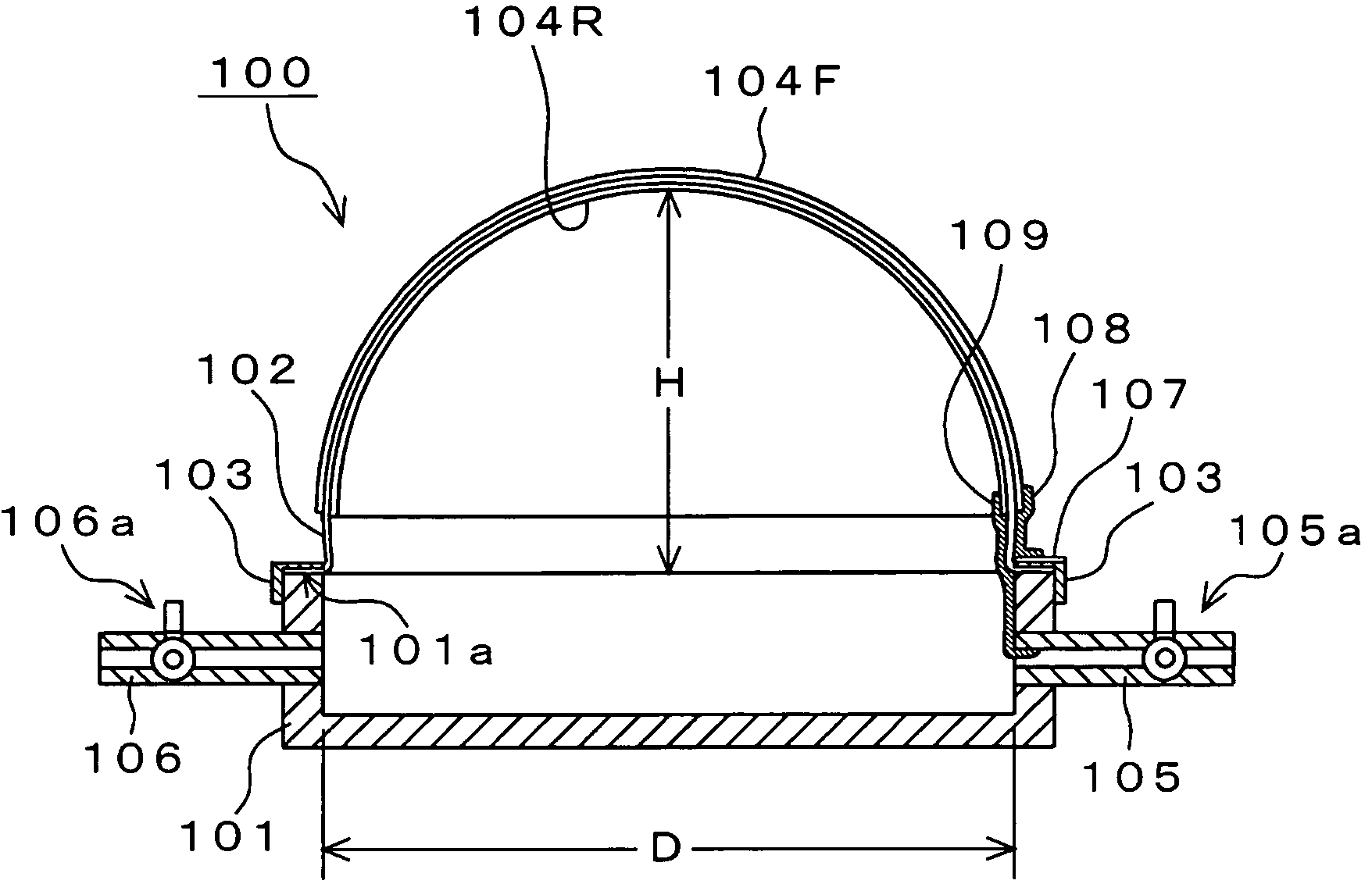
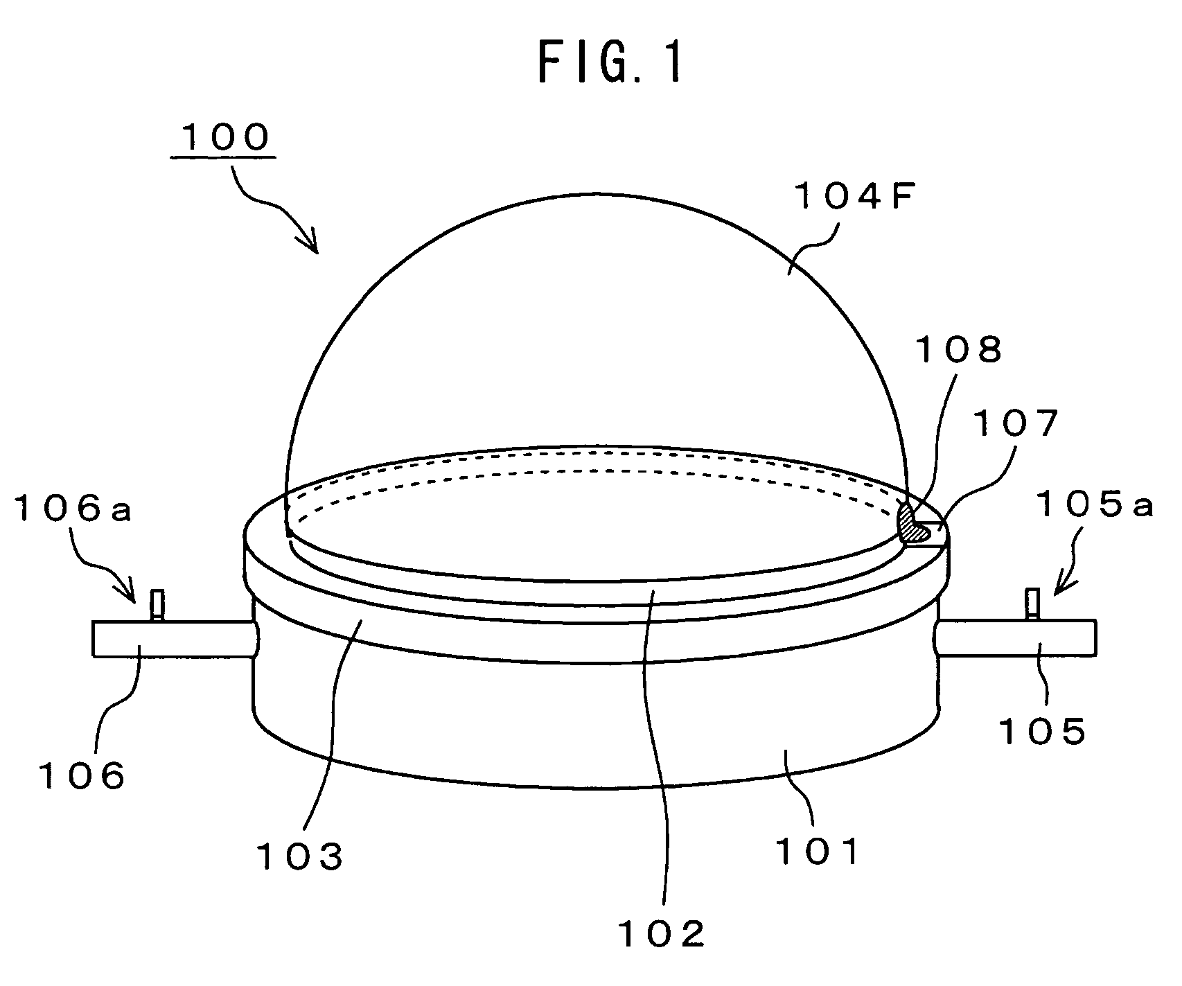
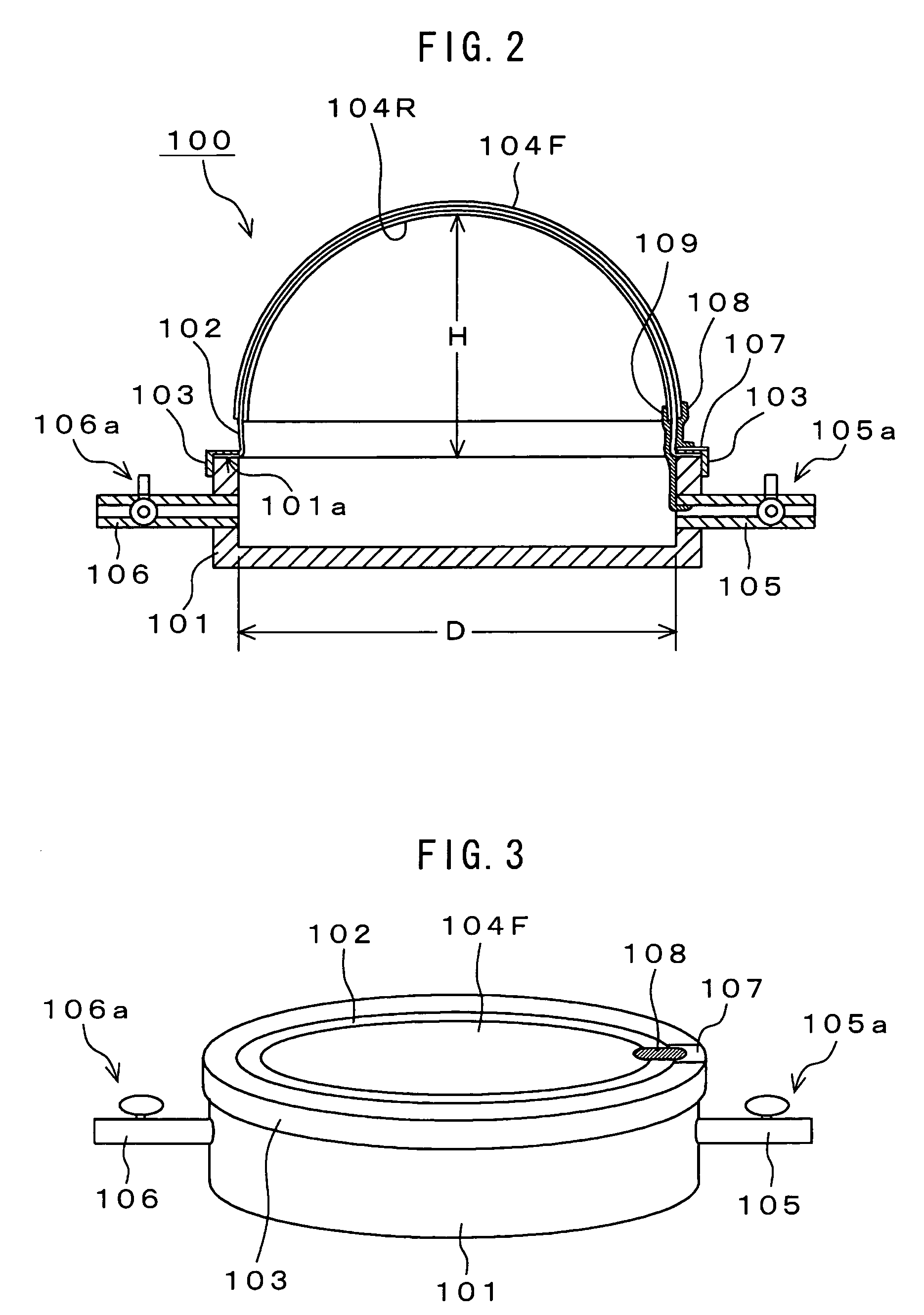
[0020]The following will describe embodiments of an electroacoustic transducer of a preferred embodiment of the present invention with reference to drawings. FIG. 1 shows a configuration of the electroacoustic transducer 100 according to an embodiment of the invention. FIG. 2 is a cross-sectional view thereof.

[0021]In the electroacoustic transducer 100, the diaphragm 102 is attached to an opening end 101a of the cup chamber 101. In this case, a ring-shaped retainer 103 retains an end portion of the diaphragm 102 on the opening end 101a of the cup chamber 101. Thus, retaining the diaphragm 102 on the opening end 101a of the cup chamber 101 enables any enclosed space to be formed within the chamber 101.

[0022]The diaphragm 102 is made of deformable electrostrictive polymer. As the deformable electrostrictive polymer, acrylic elastomer VHB 4910 manufactured by 3M can be used. It is to be noted that an end portion of the diaphragm 102 may be adhered to the opening end 101a of the cup cha...


PUM


Abstract

An electroacoustic transducer has an cup chamber and a diaphragm made of deformable electrostrictive polymer, which is attached to an opening of the chamber. The electroacoustic transducer also has first and second adaptive electrode layers formed on a front surface and a rear surface of the diaphragm, across which audio signal voltage biased by a direct-current biased voltage is applied. The first and second adaptive electrode layers have shapes that are adjustable according to a change in a shape of the diaphragm. The diaphragm is formed to make maximum a difference in air pressure of the front surface and the rear surface of the diaphragm, thereby forming any one of concave and convex shapes thereof.

Description

CROSS REFERENCE TO RELATED APPLICATION[0001]The present invention contains subject matter related to Japanese Patent Application JP 2005-207426 filed in the Japanese Patent Office on Jul. 15, 2005, the entire contents of which being incorporated herein by reference.BACKGROUND OF THE INVENTION[0002]1. Field of the Invention[0003]The present invention relates to an electroacoustic transducer such as a speaker using a diaphragm made of deformable electrostrictive polymer and a method for producing the diaphragm used in the electroacoustic transducer.[0004]2. Description of Related Art[0005]Proposed has been an electroacoustic transducer having a diaphragm and an electrode layers across which an audio signal voltage biased by a direct-current biased voltage is applied, that are placed on a front surface and a rear surface of the diaphragm. The electroacoustic transducer has used a difference in air pressure of the front surface and the rear surface of the diaphragm to form the concave o...

Claims


Application Information

Patent Timeline
Patent Type & Authority Patents(United States)
IPC IPC(8): H04R25/00
CPCH04R7/127
Inventor OHASHI, YOSHIOKISHIGAMI, JUNURYU, MASARU
Owner SONY CORP
Why Eureka
Try Eureka