Shielding structure of thin type monitor device

a monitor device and shielding technology, applied in the direction of electrical apparatus construction details, instruments, casings/cabinets/drawers, etc., can solve the problems of high frequency noise, labor for fixing or a peculiar member, and the cost of the device is high just as much

Inactive Publication Date: 2011-07-12
FUNAI ELECTRIC CO LTD
View PDF12 Cites 6 Cited by
  • Summary
  • Abstract
  • Description
  • Claims
  • Application Information

AI Technical Summary

Benefits of technology

[0009]It is an object of the present invention to restrain influence of the EMI onto the circuit board which is covered by the shielding box by performing grounding of the shielding box certainly without increasing the peculiar member or assembling process.
[0011]By this structure, the circumference of the process circuit board which is a circuit board that is affected by the EMI is covered by a metal plate, and the covering metal plate can be grounded. As a result, it is possible to restrain generation of adverse effect by the EMI.
[0013]In the preferred embodiment of the present invention, because the first shielding box and the second shielding box can be made stably contact with each other without using a screw or a conducting tape, it is possible to reduce steps for assembling.

Problems solved by technology

This EMI is high frequency noise.
However, by the conventional shielding box there is a case where not all the outer surfaces of the circuit boards in which influence of the EMI is desired to restrain, can be shielded.
Further, because the shielding box is grounded by screw fixing or a conducting tape, labor for fixing or a peculiar member is required.
As a result, cost for the device becomes high just as much.

Method used


Image

  • Shielding structure of thin type monitor device
  • Shielding structure of thin type monitor device
  • Shielding structure of thin type monitor device

Examples


Embodiment Construction

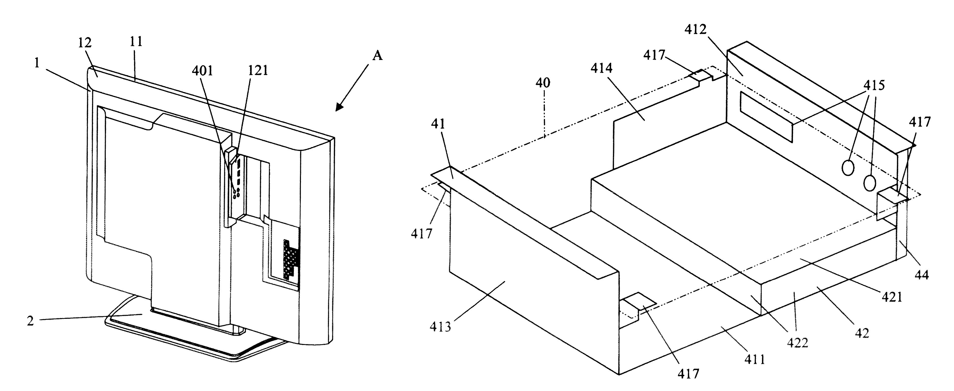
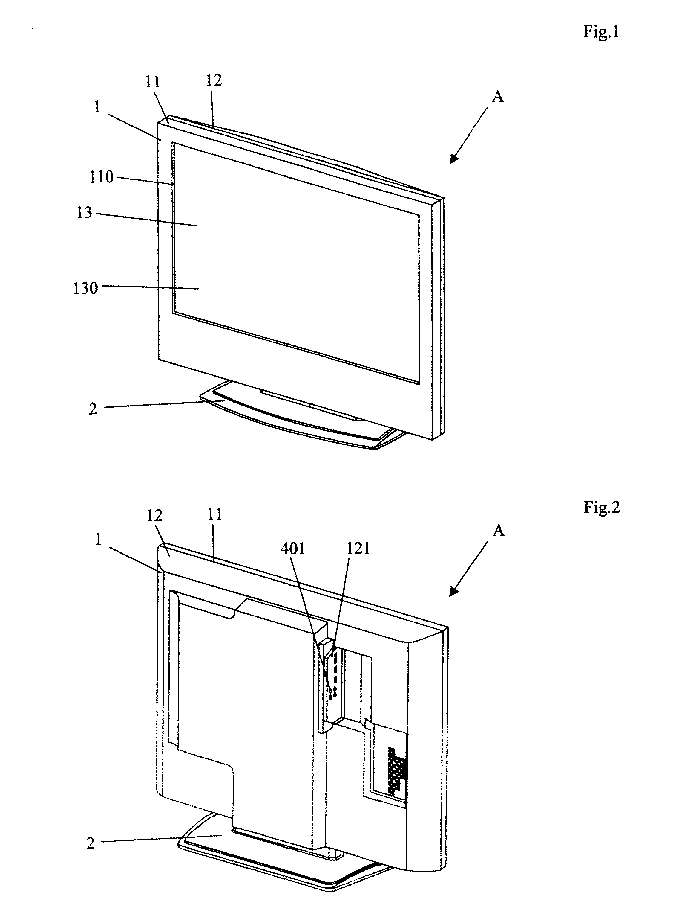
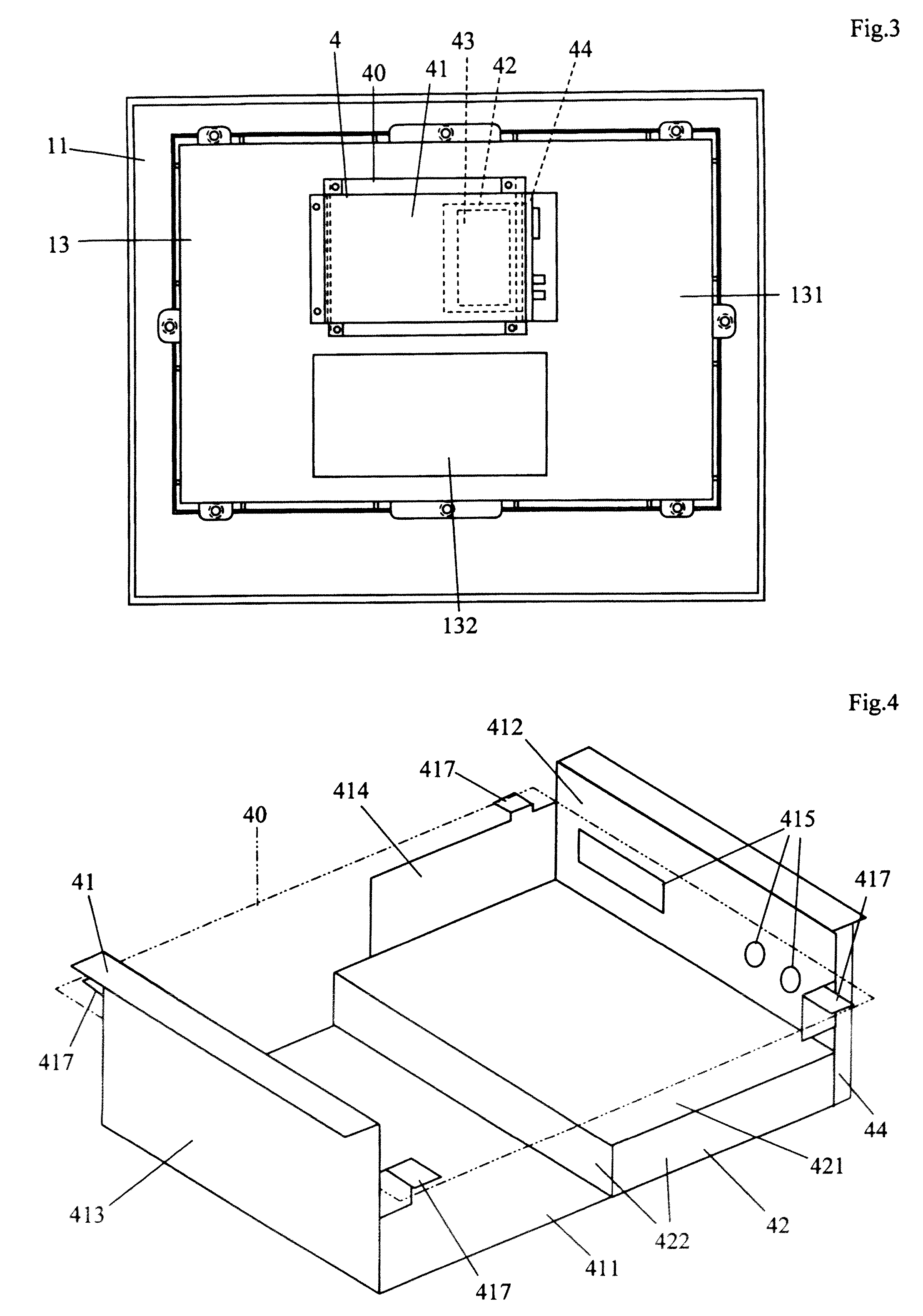
[0023]Hereinafter embodiment of the present invention will be explained with reference to drawings. FIG. 1 is a perspective view to show a liquid crystal display device which is one example of a video device that is provided with a shielding structure in accordance with the present invention when viewed from front surface side, and FIG. 2 is a perspective view of the liquid crystal display device shown in FIG. 1 when viewed from back surface side. As shown in FIG. 1 and FIG. 2, in the liquid crystal display device A at least a monitor body 1 and a stand 2 are provided. As shown in FIG. 1, the monitor body 1 is supported by the stand 2 in a state where it stands straight. At this point, in the below explanation, directions (leftward and rightward direction, upward and downward direction) of the liquid crystal display device A is based on a state where it is viewed in the stand straight state and from back surface side as far as another description is not given.

[0024]The monitor body ...


PUM

PropertyMeasurementUnit
shieldingaaaaaaaaaa
frequencyaaaaaaaaaa
rectangular shapeaaaaaaaaaa

Abstract

A shielding structure of thin type monitor device, includes: a monitor body; a first shielding box which is arranged in the monitor body, which is formed by cutting and bending a metal plate, which includes a flat plate portion having rectangular shape, and a terminal supporting portion which is formed by bending one end portion of the flat plate portion, into which a terminal is passed through, and which is fixed on a metal plate in the monitor body that is grounded; a terminal holder which includes a terminal hole which contacts with an opposite side of the terminal supporting portion with respect to the flat plate portion, through which the terminal is passed, and which forms a part of case of the monitor body; and a second shielding box which is formed by cutting and bending a metal plate, which includes a protecting portion that has a rectangular shape, that is arranged such that it contacts with the terminal supporting portion and that is made be parallel with the flat plate portion, and a standing portion which is formed by bending three sides in the protecting portion that do not contact with the terminal supporting portion and which is made contact with the flat plate portion.

Description

[0001]This application is based on Japanese Patent Application No. 2007-248554 filed on Sep. 26, 2007, the contents of which are hereby incorporated by reference.BACKGROUND OF THE INVENTION[0002]1. Field of the Invention[0003]The present invention relates to shielding structure of an input output terminal portion of a thin type monitor device.[0004]2. Description of Related Art[0005]A connecting terminal to connect with an external device such as a DVD recorder, a game machine, and the like is provided with a thin type monitor device. The connecting terminal includes an input terminal to which a signal from the external device is input, and an output terminal from which a signal is output to the external device. Further, there is a case where a tuner terminal to receive a broadcast signal of television broadcast is also provided with the thin type monitor device.[0006]In a conventional thin type monitor device, the signal which is dealt with between the thin type monitor device and ...

Claims


Application Information

Patent Timeline
Patent Type & Authority Patents(United States)
IPC IPC(8): G02F1/1333H05K5/04
CPCH05K9/0022H05K9/0054G02F2001/133334G02F1/133334
Inventor TSUTSUMI, TAKASHIMORITA, SHINJI
Owner FUNAI ELECTRIC CO LTD
Why Eureka
Try Eureka