
Luminaire and lighting arrangement

a technology of luminaires and lighting, applied in the field of luminaires, can solve the problems of not being considered aesthetically pleasing, increasing the cost of such luminaires, and not being particularly suitable for urban lighting environments, and achieve the effect of dynamic aesthetic appearan

Inactive Publication Date: 2016-12-22
SIGNIFY HLDG BV
View PDF0 Cites 4 Cited by
  • Summary
  • Abstract
  • Description
  • Claims
  • Application Information

AI Technical Summary

Benefits of technology

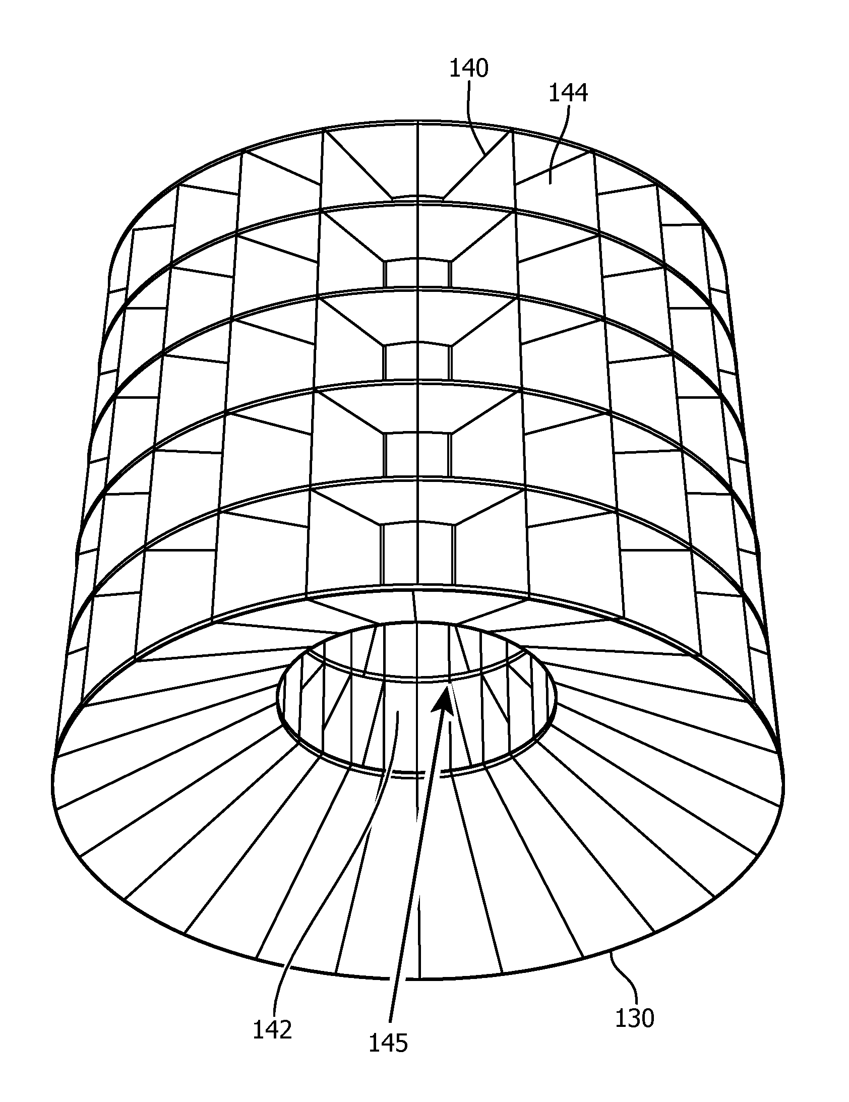
The patent is about a new type of luminaire that uses advanced technology to create a dynamic kaleidoscopic effect that improves the appearance of the luminaire. The luminaire includes an axial arrangement of SSL elements and a body with a plurality of optical cells that reflect the luminous output of the SSL elements. The body can be rotated relative to the axial carrier or vice versa. The optical cells are arranged in at least one array, with the inlet of each cell being smaller than its outlet, tunnelling the light into the cell. The body can have multiple arrays in a stack to create a particularly elaborate kaleidoscopic effect. The optical cells have inner walls that reflect the incident light multiple times, creating the desired kaleidoscopic effect. The light is then projected onto a diffusive cover, creating a diffused and homogeneous output. The luminaire can include solid state lighting elements emitting different colors, allowing for the creation of different color patterns. The technical effects of this patent include improved appearance, dynamic kaleidoscopic effect, and enhanced color capabilities.

Problems solved by technology

However, such dynamic variations of the lighting pattern may be beneficial for functional reasons but may not be considered aesthetically pleasing.
In addition, the cost of such luminaires is significantly increased due to the requirement of motion detection sensors or the like and appropriate controllers responsive to such sensors that control the luminous output of the luminaire.
However, such an arrangement is relatively complex and not particularly suitable in an urban lighting environment, for instance if a luminous output may have to be generated in a particular direction to meet functional lighting requirements.

Method used


Image

  • Luminaire and lighting arrangement
  • Luminaire and lighting arrangement
  • Luminaire and lighting arrangement

Examples


Embodiment Construction

[0037]It should be understood that the Figures are merely schematic and are not drawn to scale. It should also be understood that the same reference numerals are used throughout the Figures to indicate the same or similar parts.

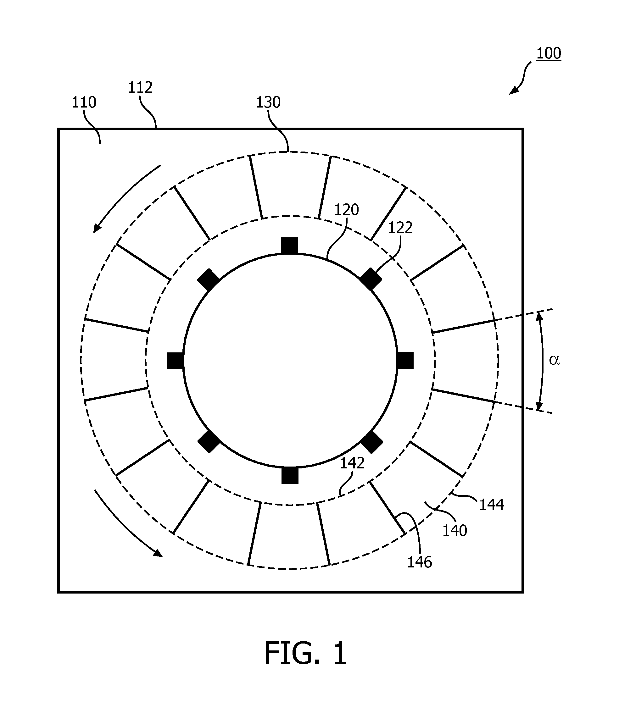
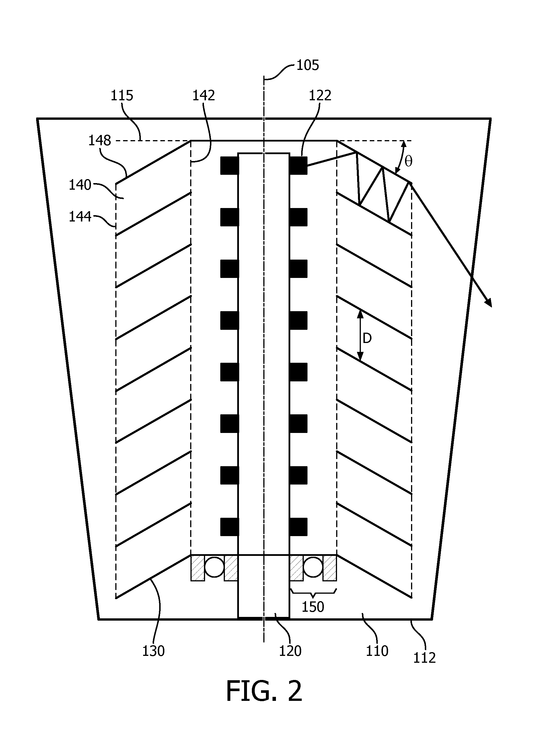
[0038]FIG. 1 schematically depicts a top view of an aspect of a luminaire 100 according to an embodiment of the present invention, whereas FIG. 2 schematically depicts a cross-section of the luminaire 100 shown in FIG. 1. The luminaire 100 comprises a chamber 110 that is delimited by at least one light exit surface 112. The number of light exit surfaces 112 is typically determined by the shape of the luminaire 100; in FIG. 1 the chamber 110 is delimited by four light exit surfaces 112, i.e. the luminaire 100 has four sides. However, it should be understood that this is by way of non-limiting example only and that the luminaire 100 may have any suitable number of light exit surfaces 112; e.g. a single light exit surface 112 in case of a cylindrical or frustoco...


PUM


Abstract

A luminaire (100) comprising a chamber (110) comprising at least one light exit surface (112); an axial carrier (120) mounted in said chamber (110) on an axis (105), said axial carrier (120) carrying a plurality of solid state lighting elements (122) and being surrounded by the light exit surface (112); and a body (130) mounted around said axial carrier (120), said body (130) comprising a plurality of radially extending optical cells (140) each comprising an inlet (142) facing said axial carrier (120); an outlet (144) facing the light exit surface (112); and a plurality of reflective surfaces (146, 148) extending from said inlet (142) to said outlet (144); wherein at least one of the axial carrier (120) and the body (130) are rotatably mounted relative to said axis (105) and wherein the body (130) can be rotated relative to the axcial carrier (120) or vice versa.

Description

FIELD OF THE INVENTION[0001]The present invention relates to a luminaire, in particular to a luminaire for illuminating an outdoor space in an urban environment such as a post-top luminaire.[0002]The present invention further relates to a lighting arrangement including such a luminaire.BACKGROUND OF THE INVENTION[0003]Urban landscape lighting such as road lighting, street lighting, square lighting and so on is commonplace in many urban areas to provide illumination of such areas, which for instance is important for safety and security reasons. Many types of luminaires are used for urban landscape lighting, such as for instance post-top lighting, column lighting, bollard lighting and so on.[0004]The functional lighting provided by such luminaries typically has to meet specific regulations in order to ensure that appropriate lighting levels are provided in a safe manner, e.g. by ensuring that glare levels produced by the luminaire are kept below defined thresholds.[0005]Consequently, ...

Claims


Application Information

Patent Timeline
IPC IPC(8): F21V14/04F21V17/02F21V3/00F21V7/00F21S8/08
CPCF21V14/04F21V7/0083F21S8/088F21Y2113/13F21V17/02F21Y2115/10F21V3/00F21V11/02F21V14/02F21V14/08F21W2131/103F21Y2107/30
Inventor SONG, GANGYAN, CAIJIE
Owner SIGNIFY HLDG BV
Learn More