
Dynamic memory architecture employing passive expiration of data

a dynamic memory and data technology, applied in the field of memory devices, can solve problems such as reducing memory and/or processing bandwidth, and achieve the effect of substantially reducing the cost of manufacturing a cache memory in accordance with the techniques of the present invention

Active Publication Date: 2009-01-15
GLOBALFOUNDRIES U S INC
View PDF5 Cites 19 Cited by
  • Summary
  • Abstract
  • Description
  • Claims
  • Application Information

AI Technical Summary

Benefits of technology

This approach reduces the need for periodic refresh operations, minimizing disruptions and overhead, allowing for more flexible and efficient data management in cache memory systems, while maintaining data validity by detecting expired data only when it is accessed.

Problems solved by technology

Thus, the rate at which refreshing occurs in the overall memory is typically based on a worst-case statistical analysis, which often represents an overburden to the processor system.
Moreover, after a read operation is performed, the contents of a dynamic memory cell must be restored because the sensing required to detect the state of the memory cell also destroys its contents.
Periodic refresh actions also undesirably stall other pending processor requests, thereby reducing memory and / or processing bandwidth.
One disadvantage with this approach, however, is that it requires substantial overhead to administer the restore tracking system so that the system is a priori aware of the fact that certain data in the dynamic memory cells might be erroneous, and to ensure that such data is not inadvertently used.

Method used


Image

  • Dynamic memory architecture employing passive expiration of data
  • Dynamic memory architecture employing passive expiration of data
  • Dynamic memory architecture employing passive expiration of data

Examples


second embodiment

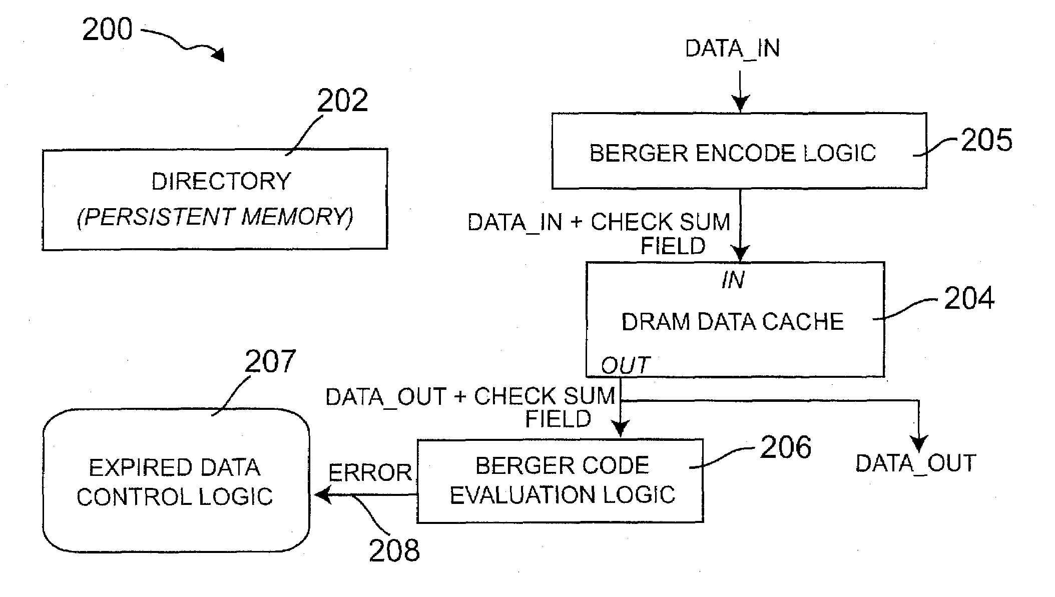
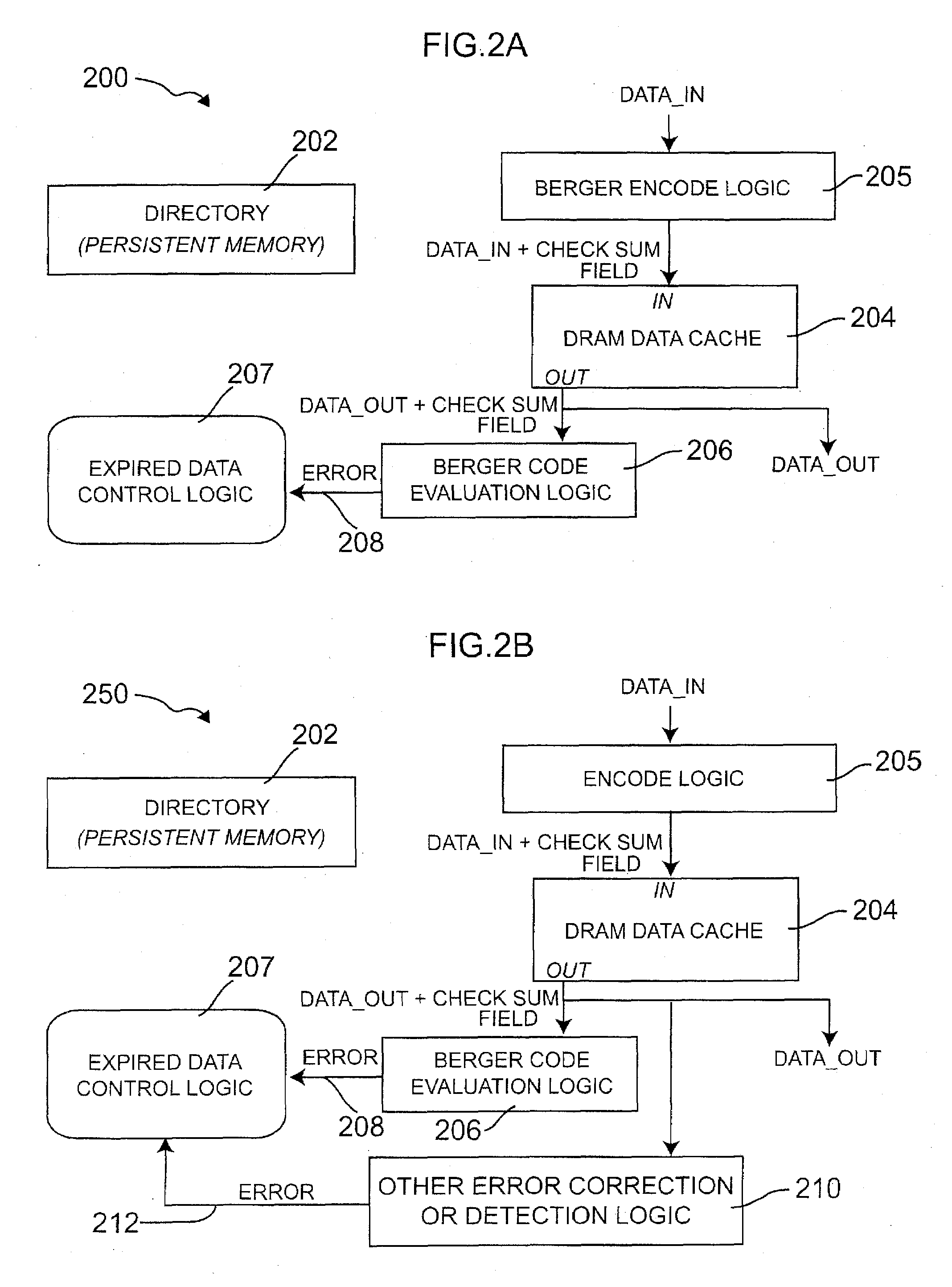
[0035]FIG. 2B is a block diagram depicting an exemplary cache memory system 250, formed in accordance with the invention. The cache memory system 250, like cache memory system 200 shown in FIG. 2A, employs a passive expiration methodology for detecting expired data stored in dynamic memory associated with the cache memory system. Unlike cache memory system 200, however, the exemplary cache memory system 250 is suitable for use where bidirectional errors are present. Bidirectional errors, which are characteristic of static random access memory (SRAM), may be defined as a mixture of one-to-zero and zero-to-one errors (often referred to simply as “errors”). Hence, an implicit notion in existing cache literature, which is generally predicated on SRAM, is that errors are essentially always bidirectional. Bidirectional errors may be detected using, for example, standard parity check codes which will detect, although not necessarily locate, an odd number of errors. More powerful error corr...

third embodiment

[0039]FIG. 4 is a block diagram depicting an exemplary cache memory system 400, formed in accordance with the invention. The cache memory system 400, like the cache memory architectures shown in FIGS. 2A and 2B, employs a passive expiration methodology for detecting expired data stored in dynamic memory associated with the cache memory system. Cache memory system 400, like cache memory system 250, is configured to handle bidirectional errors. Cache memory system 400 preferably comprises a directory 404, which preferably holds requested addresses and indicates whether or not data corresponding to the addresses is stored in the cache memory system, a time stamp memory 406, which preferably holds refresh status bits, a timer 418, or alternative counter, a DRAM data cache 410, or alternative dynamic memory, hit logic 408, and refresh control logic 402. In contrast to the cache memory systems 200 and 250, cache memory system 400 does not employ Berger encoding. Rather, the passive expira...


PUM


Abstract

Apparatus for passively tracking expired data in a dynamic memory includes a time stamp memory configurable for storing information relating to a refresh status of one or more corresponding data entries in the dynamic memory. The apparatus further includes a timer configurable for defining a desired window of time in which a refresh operation of data in the dynamic memory is to occur in order to ensure that the data is valid. Control circuitry is coupled to the time stamp memory and to the timer. The control circuitry is operative to manage the information stored in the time stamp memory relating to the refresh status of the one or more corresponding data entries in the dynamic memory.

Description

CROSS-REFERENCE TO RELATED APPLICATION(S) [0001]This application is a divisional of U.S. application Ser. No. 10 / 977,432 filed on Oct. 29, 2004, the disclosure of which is incorporated herein by reference.FIELD OF THE INVENTION [0002]The present invention relates generally to memory devices, and more particularly relates to dynamic memory implemented in a cache memory hierarchy.BACKGROUND OF THE INVENTION [0003]Recent trends in processor architecture design often involve adding more processor cores on a given integrated circuit (IC), and enabling more threads per core. This trend has driven the demand for on-chip secondary cache memory, often referred to as Level-2 (L2) cache. As the aggregate processing power of an IC grows, the capacity of the corresponding cache memories must grow accordingly. Hence, there is a renewed demand for very dense (e.g., about one gigabit (Gb) or higher) on-chip storage. While dynamic storage (e.g., dynamic random access memory (DRAM), gain-cells, etc.)...

Claims


Application Information

Patent Timeline
Patent Type & Authority Applications(United States)
IPC IPC(8): G06F12/12G11C29/00
CPCG06F11/1064G06F12/0893G06F2212/1056G11C7/1006Y02B60/1225G11C11/4096G11C2029/0411G11C2207/2245G11C2211/4062G11C11/406Y02D10/00
Inventor EMMA, PHILIP GEORGEMONTOYE, ROBERT KEVINREOHR, WILLIAM ROBERT
Owner GLOBALFOUNDRIES U S INC
Learn More