Medical imaging environment compatible positioning arm

a technology of positioning arm and medical imaging environment, which is applied in the direction of machine support, application, surgical instrument support, etc., can solve the problems of increasing the difficulty of independent locking of all of the additional joints of such a device, the difficulty of adjusting the inability to adjust the position of the positioner, etc., to achieve the effect of convenient and convenient means of locking and greater flexibility in the movement of the workpi

Active Publication Date: 2005-02-22
THE JOHN HOPKINS UNIV SCHOOL OF MEDICINE
View PDF10 Cites 18 Cited by
  • Summary
  • Abstract
  • Description
  • Claims
  • Application Information

AI Technical Summary

Benefits of technology

There has been summarized above, rather broadly, the background that is related to the present invention in order that the context of the present invention may be better understood and appreciated. In this regard, it is instructive to also consider the objects and advantages of the present invention.
It is an object of the present invention to provide a positioning device that provides greater flexibility in how a workpiece is moved as it is being positioned from one position to another in a workspace of interest.
It is another object of the present invention to provide a positioning device that provides an easier and more convenient means for locking the various elements or legs of such a device into a desired orientation.
It is yet another object of the present invention to provide a positioning device that is compatible with use in a medical imaging environment.

Problems solved by technology

However, these positioners generally do not provide great flexibility in how a workpiece can be moved as it is being positioned from one point to another in a workspace of interest.
However, this solution can quickly become unworkable as the task of independently locking all of the additional joints of such a device becomes exceedingly cumbersome.
However, a barrier can often exist to the use of commercially available positioners in many of these new medical procedures.
However, difficulties are encountered in obtaining accurate images when disruptions and deflections in the scanner's magnetic field are experienced due to the presence in the field of materials (e.g., metals) that produce a magnetic field and / or are susceptible to producing their own magnetic fields when placed within an external magnetic field.

Method used


Image

  • Medical imaging environment compatible positioning arm
  • Medical imaging environment compatible positioning arm
  • Medical imaging environment compatible positioning arm

Examples


Embodiment Construction

Before explaining at least one embodiment of the present invention in detail, it is to be understood that the invention is not limited in its application to the details of construction and to the arrangements of the components set forth in the following description or illustrated in the drawings. The invention is capable of other embodiments and of being practiced and carried out in various ways. Also, it is to be understood that the phraseology and terminology employed herein are for the purpose of description and should not be regarded as limiting.

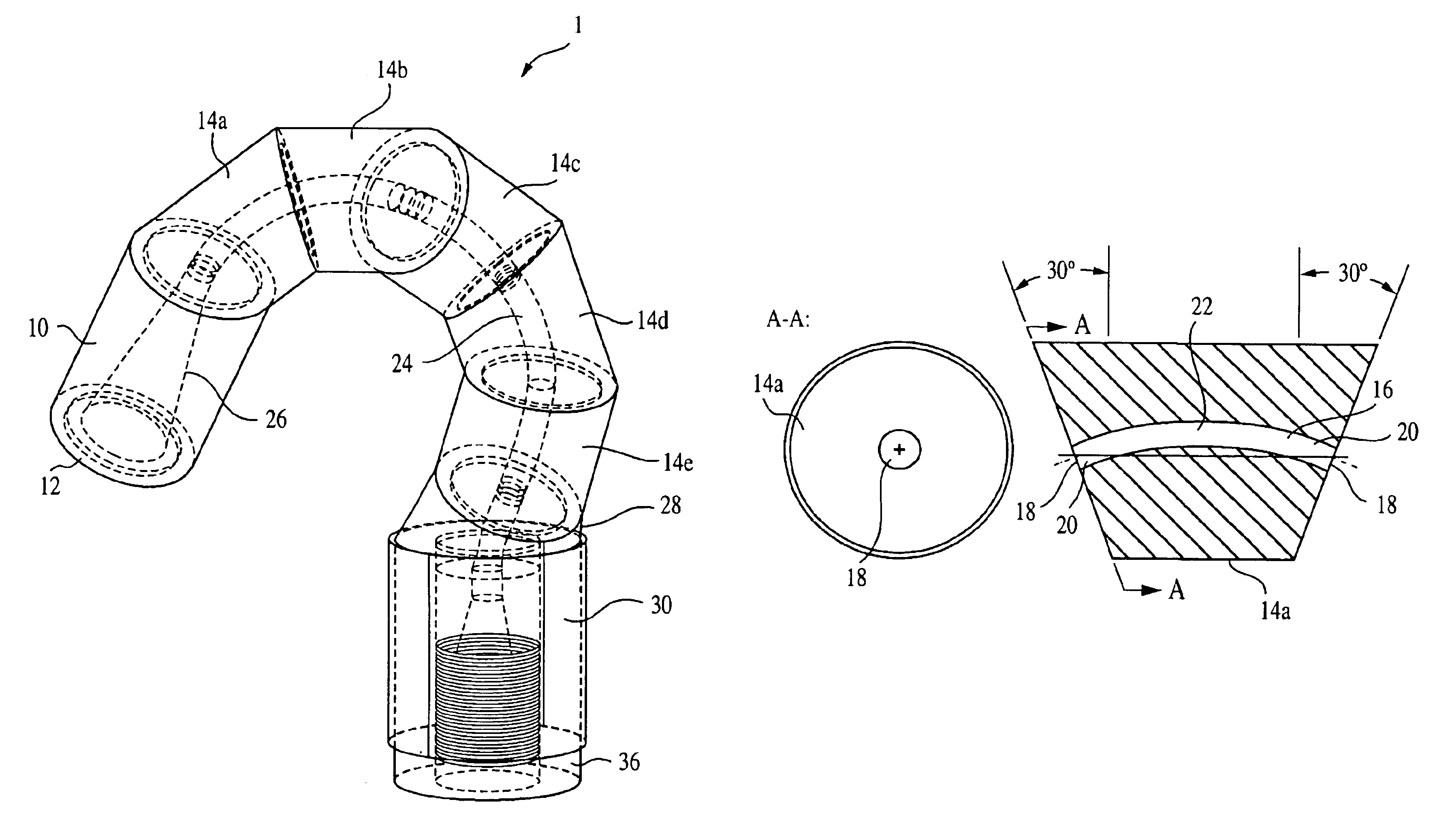
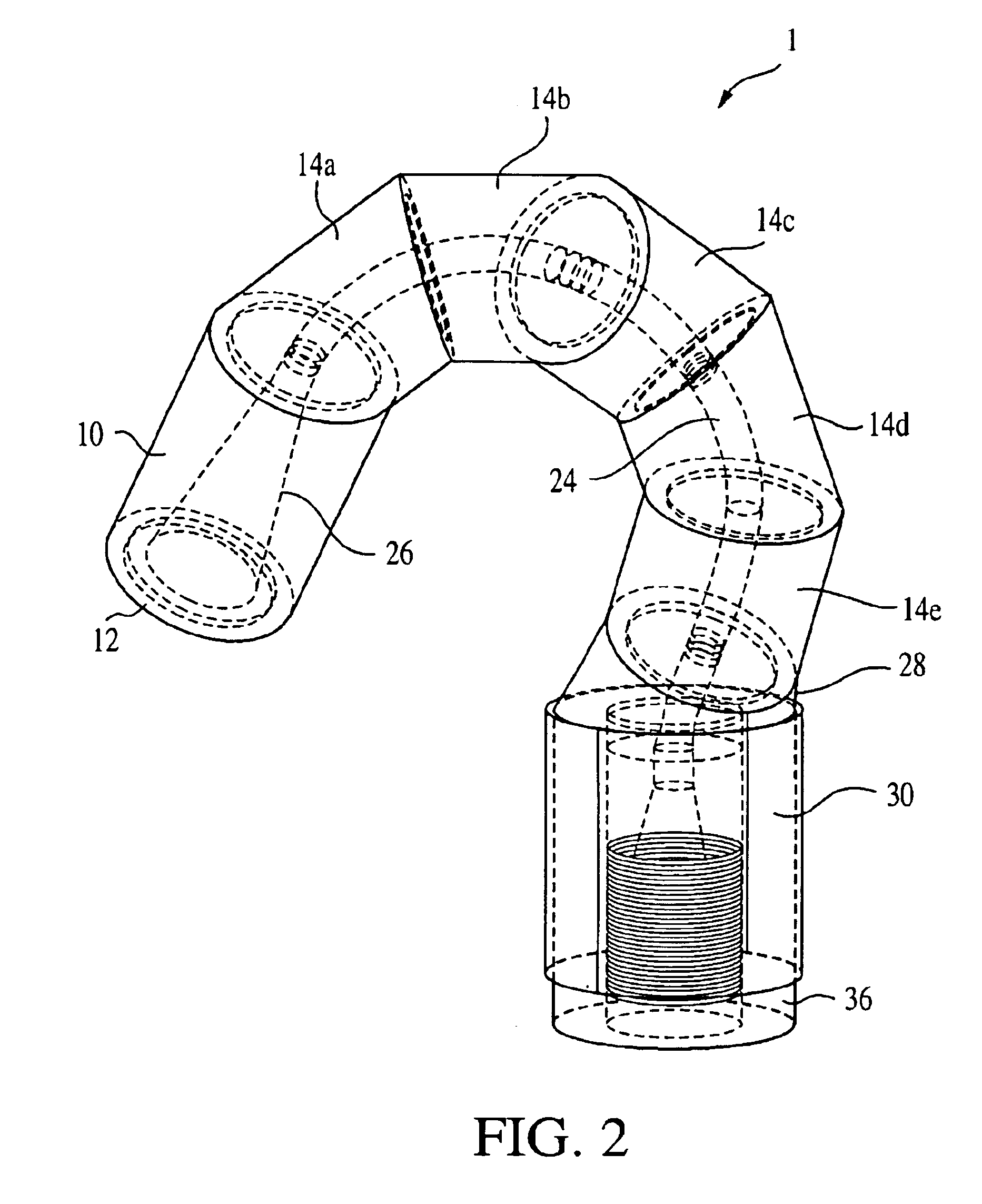
For most medical imaging applications (e.g., X-ray. MRI, ultrasound), the present invention generally relates to positioning devices that are made with materials that have low magnetic susceptibility and produces minimal, if any, magnetic fields. For example, materials such as plastics (e.g., polyetherimide, kevlar, nylon), glass, ceramics, rubbers, etc.

MRI has become the preferred method for high-resolution soft-tissue imaging for pre / p...


PUM


Abstract

A positioning arm for positioning and holding a device within a medical imaging environment workspace has: (a) a free-end link in the form of a circular cylinder having a distal end face and an adjoining end face, with the adjoining end face forming a specified angle with the cylinder's centerline and the distal end face adapted to allow for the connection of the device to the free-end link, (b) a plurality of intermediate links, each in the form of a circular cylinder having end faces that form a specified angle with the links' centerline, and each of these intermediate links having a channel connecting their end faces, (c) a base link in the form of a circular cylinder having a base end face and an adjoining end face, with the adjoining end face forming a specified angle with the link's centerline and the base end face adapted to allow for the connection of the arm to a supporting surface, (d) a cable that passes through the link channels so that one cable end attaches to the free-end link and the other end attaches to the base link, and (e) a locking mechanism that attaches to the cable and applies tension to the cable so as to pull adjoining end faces into contact so as to lock them together by frictional, wherein these components are fabricated from MRI compatible materials (e.g., plastics, glass, ceramics, rubbers, composites, and certain non-ferrous metals such as aluminum, titanium, brass, and nitilol).

Description

BACKGROUND OF THE INVENTION1. Field of the InventionThis invention relates to geometrical instruments and probe support devices. More particularly, the present invention relates to positioners or holders that are designed to position a small-working-volume instrument, held at the positioner's distal end, at a precise location in a larger work space. One embodiment of the present invention relates to a passive positioning arm that can hold a medical robot or instrument in a medical imagining environment.2. Description of Prior ArtMany, modern, high precision devices (e.g., medical robots, instruments and tools) have relatively small work volumes or workspaces. A large, work-volume positioner capable of precisely positioning such devices at any location within a specified workspace is needed for the practical implementation of such small-workspace devices.There exist many commercially available positioners and workpiece holders for these purposes. These positioners usually consist of ...

Claims


Application Information

Patent Timeline
Patent Type & Authority Patents(United States)
IPC IPC(8): A61B19/00F16M11/20F16M11/40F16M11/12F16M11/18
CPCA61B19/26F16M11/40F16M11/12A61B90/50
Inventor STOIANOVICI, DANWYROBEK, KEENAN A.MAZILU, DUMITRUWHITCOMB, LOUIS L.
Owner THE JOHN HOPKINS UNIV SCHOOL OF MEDICINE
Why Eureka
Try Eureka