Storage tank for a cryogenic fluid with a partitioned cryogen space

a cryogenic fluid and storage tank technology, which is applied in the direction of fixed capacity gas holders, gas/liquid distribution and storage, vessel construction details, etc., can solve the problems of increasing the bulk temperature and pressure of the cryogenic fluid, slowing down the density of the liquefied gas, and reducing the robustness of the valve mechanism, so as to improve the robustness of the valve, the effect of simplifying the valve mechanism

Active Publication Date: 2012-01-31
WESTPORT FUEL SYST CANADA INC
View PDF23 Cites 20 Cited by
  • Summary
  • Abstract
  • Description
  • Claims
  • Application Information

AI Technical Summary

Benefits of technology

[0010]In a preferred embodiment the valve member is spherical in shape. Persons familiar with the technology involved here will understand that other shapes are possible. An advantage of a spherical shape is that it is relatively easy to manufacture and it is not necessary to guide the movement and orientation of the valve member for it to seat properly in the seated position. This preferred arrangement simplifies the valve mechanism, improving the robustness of the valve, which is desirable since the valve is installed in a location that is difficult to access for repair. The simple design also reduces manufacturing and assembly costs. The valve member can be made from materials selected from the group consisting of metallic materials and ceramic materials. These materials are suitable for use in a cryogenic environment. While metallic materials such as stainless steel have been tested in a prototype cryogenic storage tank, persons familiar with the technology involved here will understand that other suitable materials known to be durable in a cryogenic environment could be substituted, such as other metallic materials like carbon steel, or non-metallic materials such as polytetrafluoroethylene or glass.
[0025]As already described in describing the preferred embodiments of the apparatus, the method can comprise venting vapor from the main storage space through the fill conduit prior to re-filling the storage tank with cryogenic fluid. This reduces the number of conduits that extend between the outside environment and the cryogen space, helping to reduce heat leak into the cryogen space. This arrangement also allows the method to further comprise venting vapor through the fill station hose to pre-cool it prior to delivering cryogenic fluid to the storage tank. Vapor vented through the fill hose can be directed to the fill station where it can be condensed and re-liquefied. In other circumstances the method can comprise venting vapor from the main storage space through a vent pipe prior to re-filling the storage tank with cryogenic fluid, for example if the fill station is not equipped or unwilling to receive vented vapor from the storage tank.

Problems solved by technology

Heat leak warms the cryogenic fluid, which lowers the density of the liquefied gas and increases the bulk temperature and pressure of the cryogenic fluid.
If a storage tank is filled completely with a liquefied gas, without reserving a vapor-filled ullage space, even a very small amount of heat leak can result in a rapid increase in storage pressure, because there is little space into which the liquefied gas can expand.
A problem with this arrangement is that although the flow area of the passage means is smaller than the cross-sectional flow area of the fill line, it can still allow a quantity of liquefied gas to flow into the ullage space during filling, especially when the passage means is located near the bottom of the partition to assist with draining liquefied gas back into the main tank.
Perhaps more importantly, another problem with this arrangement is that the flow restriction caused by the passage means also acts to restrict flow of the cryogenic fluid from the ullage space back into the main tank.
This is common for storage tanks used to carry fuel for a vehicle engine because completely emptying the storage tank will leave the vehicle out of fuel and stranded.
At the end of the filling process, the restricted flow of liquefied gas from the ullage space can result in a significant amount of liquefied gas being trapped inside the ullage space, resulting in a reduced volume reserved for vapor.
This outcome is disadvantageous because a reduced volume of vapor at the end of the re-filling process means that there is less volume for cryogenic fluid to expand into, which in turn means shorter hold times before vapor is vented from the cryogen space.
Also, during use after re-filling, if the liquefied gas is being delivered from the storage tank at a high rate, another disadvantage of storage tanks with one restricted fluid passage through the partition is that the flow restriction provided by the single fluid passage can slow down the rate at which the liquefied gas can be delivered.
This prevents liquefied gas from flowing into the ullage tank during the first part of the filling process, but the small diameter of the provided passage still restricts the rate at which liquefied gas can flow back into the main tank.
However, this design introduces new problems because it relies upon a pressure differential between the ullage tank and the main tank to remove liquefied gas from the ullage tank and this can also result in liquefied gas being trapped inside the ullage tank.
The effectiveness of the storage tank taught by the '908 patent can be compromised if heat transfer through the partition wall between the main tank and the ullage tank cools the vapor in the ullage tank to such a degree that it condenses vapor in the ullage space thereby reducing vapor pressure therein.
If the pressure differential is not high enough to effectively remove the liquefied gas from the ullage space through the vertical passage, when the tank is re-filled this can result in the reserved vapor space being smaller than desired.
In addition, another disadvantage of the design taught by the '908 patent is that, because of the small diameter of the vertical passage between the ullage space and main tank, it appears that blockage of the passage is possible, leading the developers of this design to introduce into preferred embodiments a pressure relief device operative to prevent over-pressurization of the ullage space, adding to the cost of manufacture, as well as adding to the possible failure modes should the pressure relief valve fail.
A disadvantage of this arrangement is that the conduit between the main tank and the auxiliary tank introduces another heat transfer path into the cryogen space.
One problem with this arrangement is that at least one capillary tube is preferably associated with the low point of the ullage space so that liquefied gas that enters or condenses inside the ullage space can be drained there from through the capillary tube that is associated with the low point of the ullage space.
Since the capillary tubes remain open, they can allow flow of the cryogenic fluid into the auxiliary tank during re-filling, which can result in a reduced volume of vapor space.

Method used


Image

  • Storage tank for a cryogenic fluid with a partitioned cryogen space
  • Storage tank for a cryogenic fluid with a partitioned cryogen space
  • Storage tank for a cryogenic fluid with a partitioned cryogen space

Examples


Embodiment Construction

)

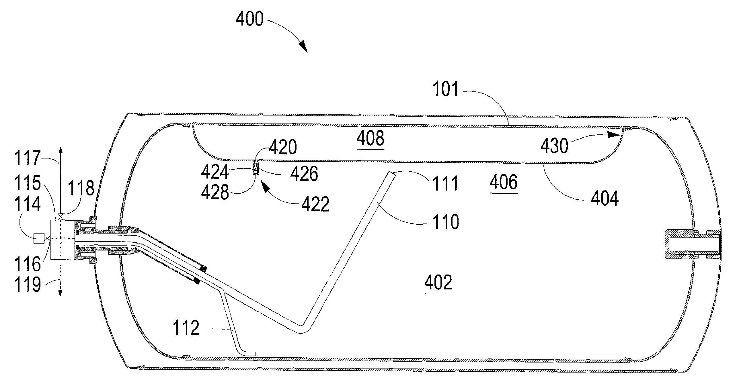
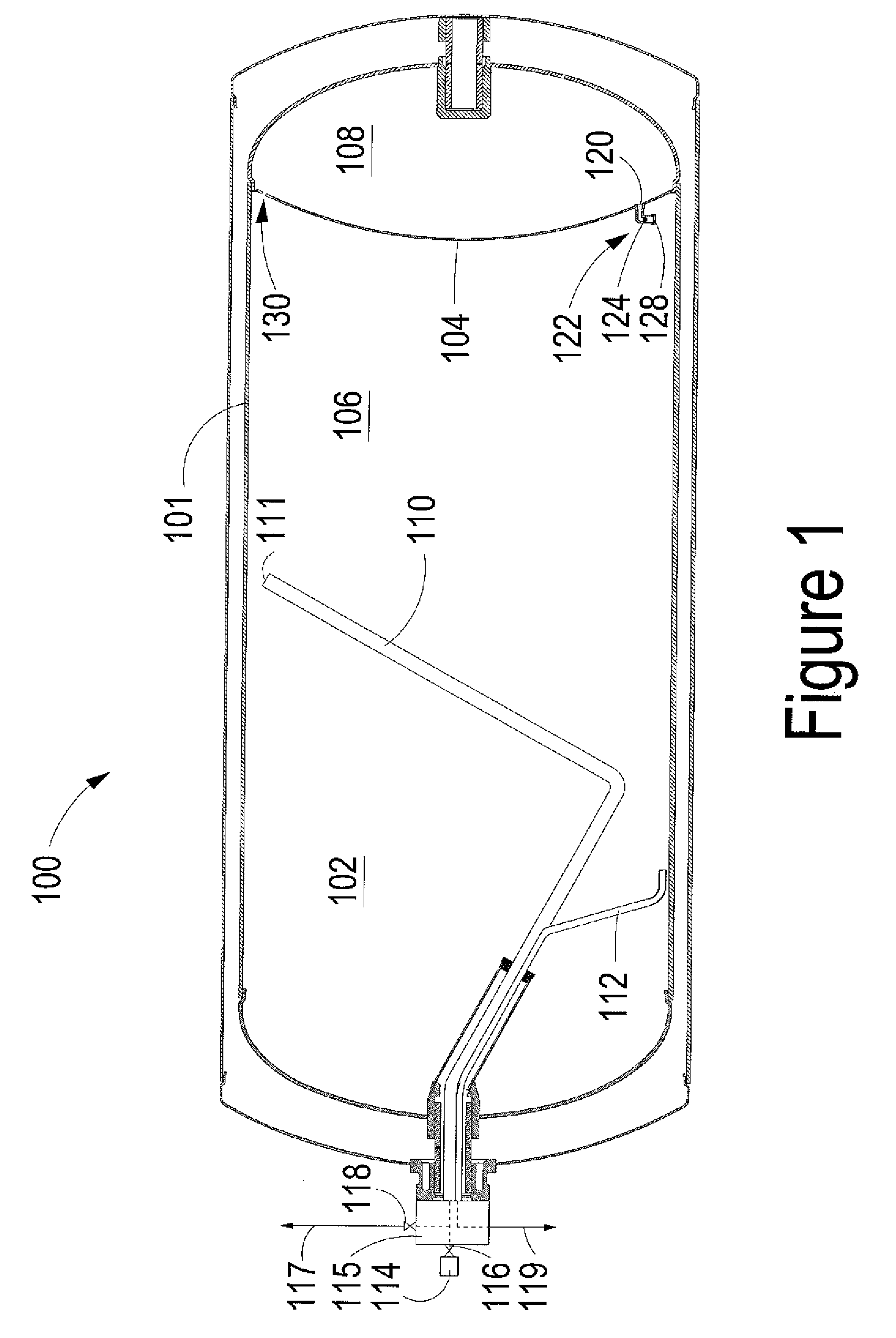
[0033]With reference to the Figures, storage tanks 100, 300 and 400 are examples of embodiments that are particularly suited for holding cryogenic fluids inside thermally insulated vessel 101, which defines respective cryogen spaces 102 and 402. FIGS. 1, 3 and 4 show that the present design can be applied to storage tanks with different configurations for the partition, and for storage tanks that are used for delivering the stored fluid at lower or relatively high pressures. For example, the embodiment of FIG. 3 shows a storage tank with an internal pump that can be used to deliver the stored fluid at a higher pressure. The different illustrated embodiments show that the present design can be useful for many different applications where such storage tanks are employed for holding and dispensing liquefied gases. For example, gases can be stored and dispensed in liquefied form to provide refrigeration for industrial processes or if the gas is used in the gaseous phase it can be store...


PUM


Abstract

A cryogenic storage tank comprises a partition that divides a cryogen space into a main storage space and an auxiliary space. A valve disposed inside the cryogen space is associated with a first fluid passage through the partition. The valve comprises a valve member that is actuatable by fluid forces within the cryogen space. A second fluid passage through the partition comprises a restricted flow area that is dimensioned to have a cross-sectional flow area that is smaller than that of a fill conduit such that there is a detectable increase in back-pressure when the main storage space is filled with liquefied gas.

Description

FIELD OF THE INVENTION[0001]The present invention relates to a storage tank for a cryogenic fluid with a partitioned cryogen space. More particularly, a partition divides the cryogen space into two storage spaces with the apparatus and method comprising at least two fluid passages through the partition and at least one valve that regulates the flow of cryogenic fluid between the two storage spaces.BACKGROUND OF THE INVENTION[0002]Cryogenic fluids comprise liquefied gases that generally have boiling points below −100° C. (about −150° F.) at atmospheric pressure. Examples of cryogenic fluids include liquefied natural gas (LNG), and other gases, such as nitrogen, oxygen, carbon dioxide, methane and hydrogen, that are storable in liquefied form at cryogenic temperatures.[0003]To prevent cryogenic fluids from boiling off and to increase the time that they can be stored in liquefied form, cryogenic fluids can be stored in thermally insulated storage tanks that consist of an inner storage ...

Claims


Application Information

Patent Timeline
Patent Type & Authority Patents(United States)
IPC IPC(8): F17C3/08
CPCF17C3/00F17C5/02F17C2201/0109F17C2201/0166F17C2201/0171F17C2201/035F17C2201/054F17C2201/056F17C2203/0304F17C2203/0391F17C2203/0629F17C2205/0323F17C2205/0332F17C2205/0335F17C2205/0352F17C2205/037F17C2205/0394F17C2209/232F17C2221/012F17C2221/013F17C2221/014F17C2221/03F17C2221/033F17C2223/0161F17C2223/033F17C2223/045F17C2223/047F17C2225/0161F17C2225/033F17C2225/035F17C2225/043F17C2225/045F17C2227/0107F17C2227/0135F17C2227/0178F17C2250/0408F17C2250/043F17C2250/0636F17C2250/072F17C2250/075F17C2260/02F17C2260/021F17C2260/031F17C2260/035F17C2265/034F17C2265/066F17C2265/07F17C2270/0168F17C2270/05F17C2270/0545F17C2270/0581Y02E60/321Y02E60/32
Inventor HARPER, GREGORY CHARLESPOST, ADRIAN
Owner WESTPORT FUEL SYST CANADA INC
Why Eureka
Try Eureka