Hand tightenable coaxial cable connector

a coaxial cable and connector technology, applied in the direction of electrical apparatus, connection, coupling device connection, etc., can solve the problems of insufficient seated connection, add to the cost and complexity of manufacturing the connector, etc., and achieve the effect of improving moldability and enhancing gripping the nu

Active Publication Date: 2011-10-04
PPC BROADBAND INC
View PDF40 Cites 82 Cited by
  • Summary
  • Abstract
  • Description
  • Claims
  • Application Information

AI Technical Summary

Benefits of technology

[0012]It is a further object of the present invention to provide a coaxial cable connector having structure to enhance hand-tightening of the nut, while minimizing the cost and complexity of manufacturing the connector.
[0014]In a preferred embodiment, the tubular body portion of the nut includes a knurled or otherwise textured outer surface to enhance gripping of the nut by hand. The knurled outer surface preferably has an uneven pattern for improved moldability, wherein the uneven pattern includes a first row of protrusions disposed along a first central axial reference plane, a second row of protrusions disposed along a second central axial reference plane perpendicular to the first central axial reference plane and a series of intermediate rows of protrusions arranged sequentially between and parallel with the first and second rows of protrusions. Each intermediate row of protrusions includes a ramp portion having an outer surface sloping in a direction from the first central axial reference plane to the second central axial plane at an angle of at least ninety degrees when measured from the first central axial reference plane to the outer surface. Also, the angle of the ramp portion outer surface of each row of the series of intermediate rows is preferably greater than the angle of the ramp portion outer surface of a preceding row when moving in a direction from the first row of protrusions to the second row of protrusions.

Problems solved by technology

However, if the connector is not sufficiently hand-tightened, the result is a connection that is not properly seated.
Obviously, this is a cost concern for the CATV, computer, satellite and telecommunication providers, who then have to send a repair technician to the customer's home.
Obviously, such an additional separate component adds to the cost and complexity of manufacturing the connector.

Method used


Image

  • Hand tightenable coaxial cable connector
  • Hand tightenable coaxial cable connector
  • Hand tightenable coaxial cable connector

Examples


Embodiment Construction

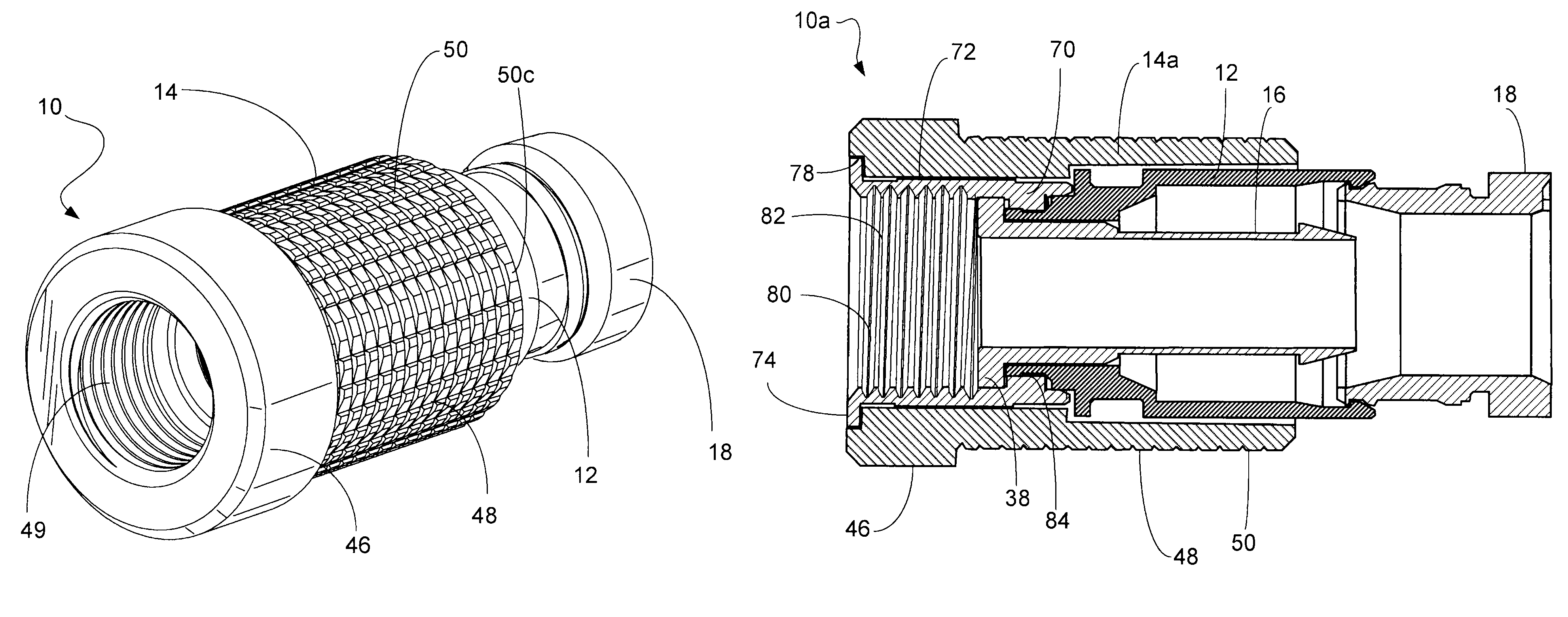
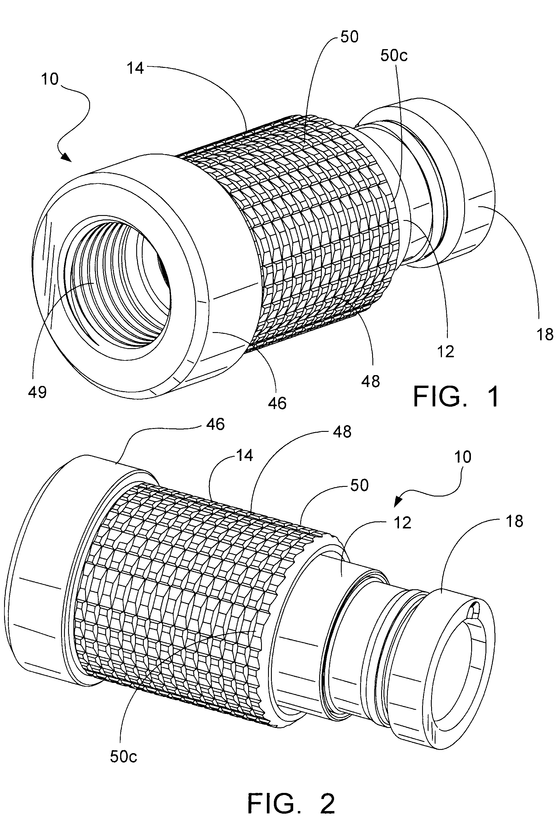
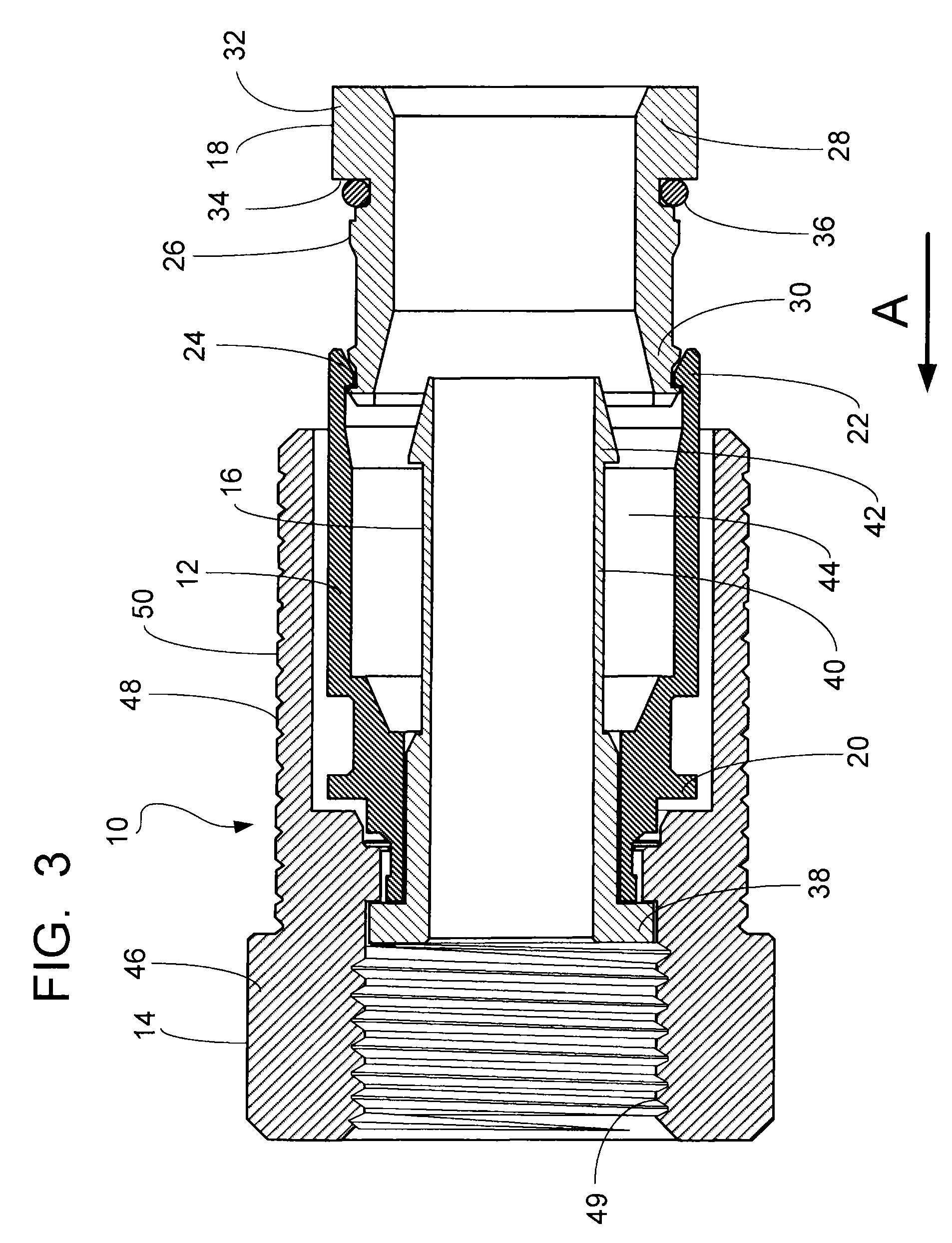
[0025]Referring first to FIGS. 1-3, a preferred embodiment of the coaxial cable connector 10 of the present invention is shown. The connector 10 generally includes a connector body 12 and a nut 14 rotatably connected to the connector body. As will be discussed in further detail below, the connector 10 of the present invention further preferably includes an annular post 16 retained within the connector body 12 and a locking sleeve 18 movably coupled to the connector body 12.

[0026]The connector body 12, also called a collar, is an elongate generally cylindrical member, which can be made from plastic or from metal or the like. The body 12 has a forward end 20 coupled to both the post 16 and the nut 14, and an opposite cable receiving end 22 for insertably receiving the locking sleeve 18, as well as a prepared end of a coaxial cable in the forward direction as shown by arrow A in FIG. 3. The cable receiving end 22 of the connector body 12 defines an inner sleeve engagement surface for c...


PUM


Abstract

A coaxial cable connector includes a connector body having a forward end and a rearward cable receiving end for receiving a cable and a nut rotatably coupled to the forward end of the connector body. The nut includes a flanged head portion at its forward end and a tubular body portion extending rearwardly from the head portion over the connector body and terminating adjacent the rearward cable receiving end of the connector body. The flanged head portion is radially enlarged, having an outer diameter greater than a maximum outer diameter of the tubular body portion, and the tubular body portion preferably surrounds more than half the length of the connector body.

Description

CROSS-REFERENCE TO RELATED APPLICATIONS[0001]This application claims the benefit of U.S. Provisional Application No. 61 / 116,770, filed on Nov. 21, 2008, and U.S. Provisional Application No. 61 / 161,599, filed on Mar. 19, 2009, the specifications of which are incorporated by reference herein in their entirety for all purposes.BACKGROUND OF THE INVENTION[0002]The present invention relates generally to connectors for terminating coaxial cable. More particularly, the present invention relates to a coaxial cable connector having an elongated patterned nut for hand-tightening.[0003]It has long been known to use connectors to terminate coaxial cable so as to connect a cable to various electronic devices such as televisions, radios and the like. Prior art coaxial connectors generally include a connector body having an annular collar for accommodating a coaxial cable, an annular nut rotatably coupled to the collar for providing mechanical attachment of the connector to an external device and ...

Claims


Application Information

Patent Timeline
Patent Type & Authority Patents(United States)
IPC IPC(8): H01R9/05
CPCH01R9/05H01R13/622
Inventor SNYDER, BRYAN S.DERENTHAL, BRIANPHILLIPS, JR., ROGERRODRIGUES, JULIO
Owner PPC BROADBAND INC
Why Eureka
Try Eureka