Rake combiner for a CDMA rake receiver

a combiner and cdma technology, applied in the field of rake combiners, can solve the problems of multipath combination, increase in etc., and achieve the effect of minimizing the cost and complexity of rake receivers

Inactive Publication Date: 2007-07-17
WSOU INVESTMENTS LLC
View PDF10 Cites 6 Cited by
  • Summary
  • Abstract
  • Description
  • Claims
  • Application Information

AI Technical Summary

Benefits of technology

[0017]This allows the phase rotation of received multipath components to be performe

Problems solved by technology

However, the use of memory in each rake finger to perform delay equalization can result in an increase in cost and complexity of the rake receiver.
Further, the use of m

Method used


Image

  • Rake combiner for a CDMA rake receiver
  • Rake combiner for a CDMA rake receiver
  • Rake combiner for a CDMA rake receiver

Examples


Embodiment Construction

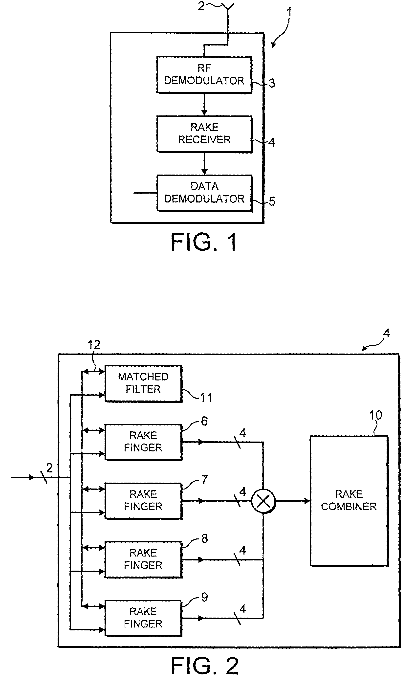
[0026]FIG. 1 shows a radiotelephone 1 suitable for use in a CDMA communication system. The radiotelephone 1 has an antenna 2 for receiving a spread spectrum RF signal. Typically the received spread spectrum signal will be transmitted as a quadrature, digitally modulated signal with a symbol period determined by the digital modulation scheme. The data structure of the signal (e.g. the logical / physical channel arrangement and the slot / frame sizes) defined in the appropriate CDMA standard (e.g. 3rd Generation Partnership Project specification TS 25.211).

[0027]The antenna 2 is connected to an input of a demodulator module 3. A spread spectrum RF signal received by the antenna 2 is provided to the demodulator module 3. The demodulator module 3 down converts the spread spectrum RF signal to a spread spectrum baseband signal, converts the baseband analog signal into a digital signal and separates the in-phase (I) and quadrature-phase (Q) components.

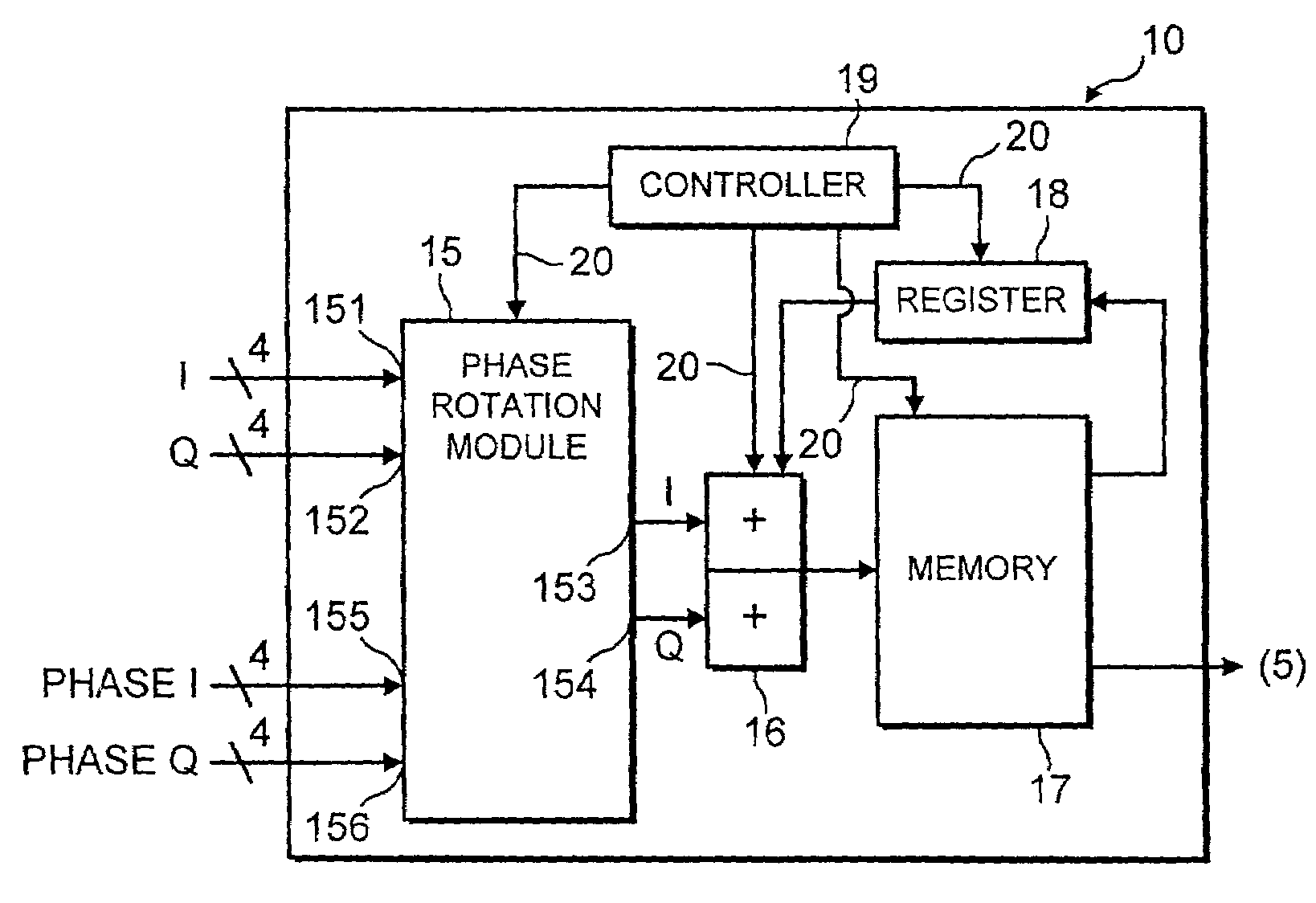
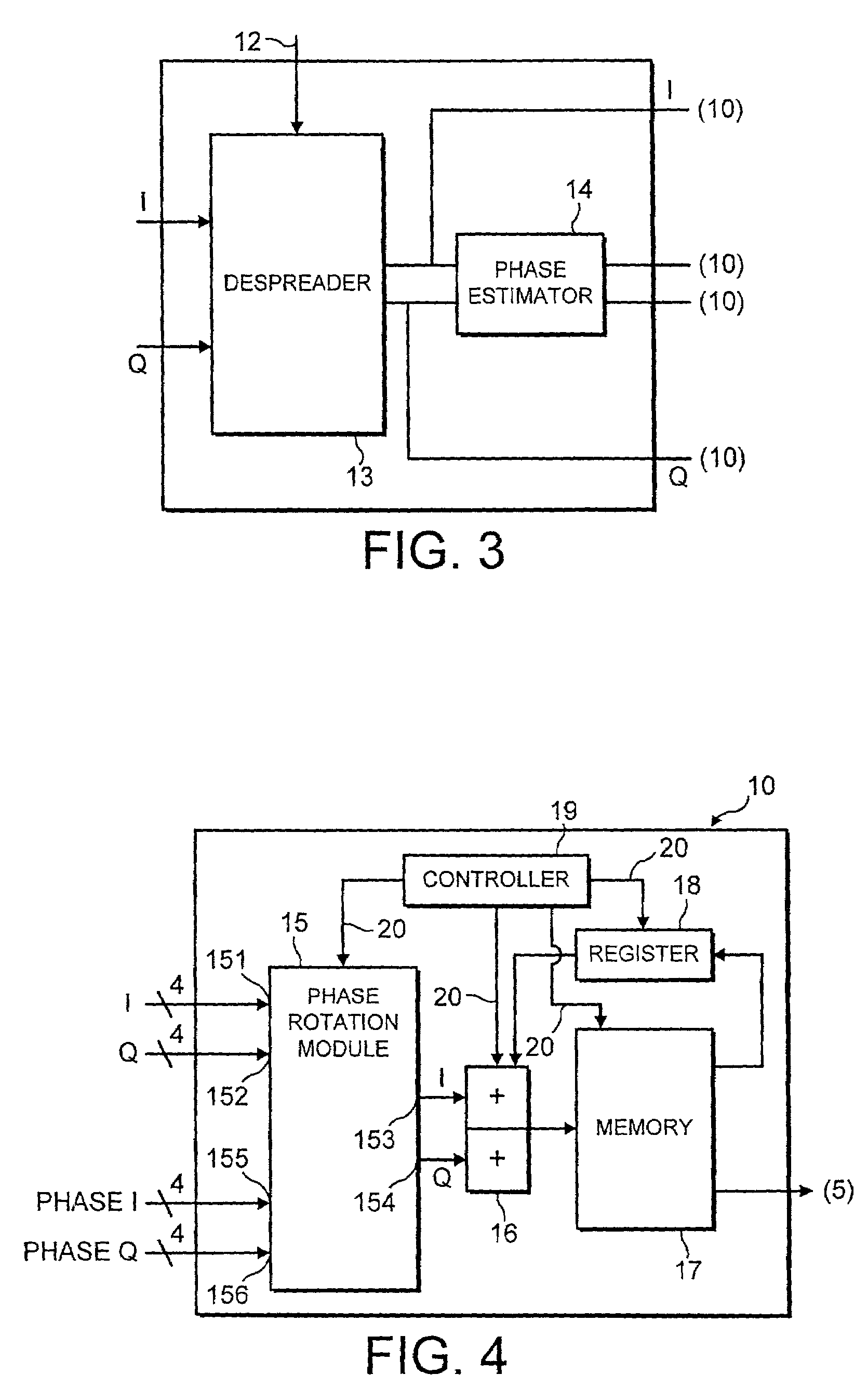
[0028]An output of the demodulator module...


PUM


Abstract

A rake combiner for a CDMA rake receiver, the combiner comprising a receiver for receiving a plurality of multipath components of a signal; a memory; a controller arranged to store a first multipath component in the memory; a summer for summing the first multipath component with a second multipath component to provide a combined signal; wherein the controller is arranged to store the combined signal in the memory.

Description

BACKGROUND OF THE INVENTION[0001]1. Field of the Invention[0002]This invention relates to a rake combiner, in particular a rake combiner for a CDMA rake receiver.[0003]2. Description of the Prior Art[0004]Multiple access communication systems allow a large number of users to establish wireless communication channels over a relatively limited frequency spectrum. One multiple access communication system that has become increasingly prominent is the spread spectrum multiple access telecommunication system, otherwise known as code division multiple access (CDMA).[0005]Multiple access in a CDMA system is achieved by assigning each user in the system a pseudo-random code, where the assigned pseudo random codes have good auto and cross-correlation properties. In use the assigned pseudo-random code is modulated with a user's hit rate signal. The bandwidth of the modulated signal incorporating the pseudo-random code is much larger than the bandwidth of the user's bit rate signal, thereby spr...

Claims


Application Information

Patent Timeline
IPC IPC(8): H04B1/00H04B1/707H04B7/26
CPCH04B1/7115H04B1/7117
Inventor WILSON, ALICE
Owner WSOU INVESTMENTS LLC
Why Eureka
Try Eureka