Sunroof system

a technology of sunroof and drive pipe, which is applied in the direction of sunroof, mechanical equipment, transportation and packaging, etc., can solve the problems of increasing the manufacturing cost, the drive pipe may ruin the whole drive system of the sunroof system, and the increase in the cost so as to reduce the manufacturing cost, the effect of reducing the weight of the sunroof system, and simplifying the assembly of the drive pip

Active Publication Date: 2011-12-13
YACHIYO IND CO LTD
View PDF8 Cites 7 Cited by
  • Summary
  • Abstract
  • Description
  • Claims
  • Application Information

AI Technical Summary

Benefits of technology

[0009]In view of such problems of the prior art, a primary object of the present invention is to provide a sunroof system in which a push-pull cable is smoothly guided by a guide pipe (drive pipe and / or idle pipe) while eliminating the need for precise bending work for the guide pipe.
[0010]A second object of the present invention is to provide a sunroof system which allows a push-pull cable and guide pipe to be assembled to a frame with ease.
[0011]A third object of the present invention is to provide a sunroof system which is protected from inadvertent deformation of the guide pipe.

Problems solved by technology

Such a drive pipe and idle pipe are required to be bent in a complex configuration, and this contributed to an increase in the cost of the sunroof system.
Because each drive pipe is required to protrude ahead of the front frame for the purpose of avoiding a sharp bending of the drive pipe, the protruding parts of the drive pipes are prone to inadvertent deformation during the handling of the sunroof assembly, and any deformation of the drive pipes may ruin the whole drive system of a sunroof system.
In the case of the sunroof system disclosed in patent document 2, the number of component parts can be reduced owing to the elimination of the drive pipes, but a highly complex die assembly is required for molding the front frame, and this increases the manufacturing cost.
Furthermore, because the guide pipe portions cannot be molded so as to entirely surround the push-pull cables, a measure is required to prevent grease from dripping from the guide pipe portions.
It is also difficult to entirely eliminate noises that are caused by the sliding contact between the cable and guide pipe portions.
The guide pipe portions are typically given with a highly complex configuration, and this tends to cause poor dimensional and geometrical precision.
If there are burrs in the guide pipe portions, the sliding engagement between the burrs and cables cause noises.

Method used


Image

  • Sunroof system
  • Sunroof system
  • Sunroof system

Examples


Embodiment Construction

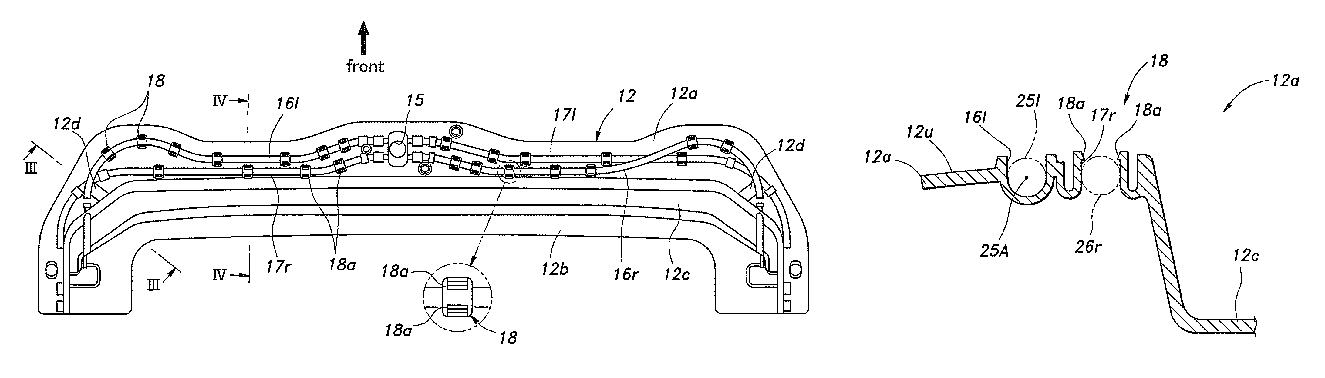
[0027]FIG. 1 generally shows a roof of an automobile incorporated with an automotive sunroof system 3 embodying the present invention. In the following description, numerals denoting some of the parts of the sunroof system 3 may be accompanied by a suffix “l” or “r” to indicate that the particular components are located on which side of the vehicle body, and such parts may be collectively denoted with the corresponding numerals without the suffix.

[0028]Referring to FIG. 1, the roof 1 of the automobile comprises a roof panel 2 having a rectangular opening 2a formed in a front part thereof and a sunroof system 3 configured to selectively close the opening 2a. The sunroof system 3 comprises a sunroof panel (closure member) 4 configured to slide in a fore-and-aft direction and tilt up and down to open and close the opening 2a in a per se known manner, a sunroof frame 10 attached to the part of the roof 1 surrounding the opening 2a and an actuator 20 for actuating the sunroof panel 4.

[00...


PUM


Abstract

In a sunroof system (3) for a vehicle using a push-pull cable (22) for actuating a sunroof panel (4), the push-pull cable is received in a drive pipe (25), and a sunroof frame (12) is provided with a drive pipe retaining feature (16, 18). Therefore, the drive pipe may be made of flexible material, and firmly held in place by the pipe retaining feature even when the push-pull cable is subjected to significant tensile and compressive load. The pipe retaining feature may include a pipe retaining groove (16) for receiving the drive pipe and clips (18) for resiliently retaining the drive pipes in the pipe retaining groove.

Description

BACKGROUND OF THE INVENTION[0001]The present invention relates to a drive system for a closure member configured to selectively close an opening of a vehicle roof, and in particular to an automotive sunroof system.[0002]In a typical automotive sunroof system, a pair of side frames each fitted with a guide rail extend in a fore-and-aft direction on either side of a roof opening. Each side frame has a front end adjacent to a front edge of the roof opening and a rear end extending further rearward from a rear edge of the roof opening. A pair of sliders supporting a slide panel are slidably supported by the corresponding guide rails, and to each slider is connected an end of a Bowden or push-pull cable which is configured to be pushed and pulled as required by an electric motor located centrally in a front frame extending along the front edge of the roof opening. Thereby, the slide panel can be moved in a fore-and-aft direction between a closed position fully closing the roof opening an...

Claims


Application Information

Patent Timeline
Patent Type & Authority Patents(United States)
IPC IPC(8): B60J7/057
CPCB60J7/0573B60J7/043
Inventor HOTTA, KOUICHIMIHASHI, AYUMI
Owner YACHIYO IND CO LTD
Why Eureka
Try Eureka