Collecting bag having improved closure and method of manufacturing such a collecting bag

a technology of collecting bag and closure, which is applied in the field of collecting bags, can solve the problems of deterioration of film or film blanks, insufficient closure of discharge portion, etc., and achieve the effect of simplifying the handling of plate members and strap members

Active Publication Date: 2012-06-26
COLOPLAST AS
View PDF17 Cites 7 Cited by
  • Summary
  • Abstract
  • Description
  • Claims
  • Application Information

AI Technical Summary

Benefits of technology

[0009]It is a further object to improve the manufacturing conditions.
[0011]The provision of the strap members has a double function of securing a proper functioning of the collecting bag during its entire period of use, and of facilitating the manufacture of the collecting bag. When manufacturing the collecting bag, the strap members provide a protection of the film blank or film blanks in the area between the facing edges of the plate members. This provides for an increased degree of freedom with respect to the choice of joining techniques. For instance, it has been made possible to utilize welding also for attaching the plate members to the respective film blank, and not only for joining the film blanks to each other. In this case the strap members absorb some of the heat necessarily involved in the welding process. In the absence of strap members this heat would deteriorate the film blank or film blanks, possibly to such an extent that the closure of the discharge portion may not be carried properly, or even that leakage occurs. Consequently, a substantial rationalization of the manufacturing process is obtained. During use of the collecting bag the strap members act as reinforcement. This entails, i.a., that the distance between the facing edges of the plate members remains substantially constant, thereby securing a reliable functioning of the collecting bag during its entire lifetime. The presence of a predetermined distance between the distal edge and the proximal edge of the first and second plate members, respectively, entails that it is possible to control the closure of the discharge portion without having to take particular precautions, as the distance may be chosen according to the materials and dimensions chosen for the film blanks, the plate members, and the strap members. The provision of a distance smaller than the total thickness of the first plate member and the second plate member ensures that there will be a tensional force acting on the second film blank when the discharge portion is folded to attain the closed folded condition. In turn, this tensional force provides a sealing force acting to press the plate members towards each other in the area of the discharge opening.
[0018]In an advantageous embodiment, at least one of the facing edges of the plate members is provided with a fillet or chamfer. This provides for a springing effect when the discharge portion is folded to attain the closed folded condition. In this manner slight deviations in the positions and / or thickness of the plate members may be compensated for. Such deviations are most often due to manufacturing conditions, and may, if not compensated for, entail uneven or skew load of the film blanks, which in worst case may lead to deterioration of the film blank, possibly to such an extent that local rupture of the film blank occurs, and / or lack of tightness of the discharge portion.
[0023]As the strap members provide a protection of the film blanks, it is possible to obtain a wider variety of joining techniques than would have been possible otherwise.
[0025]It is furthermore preferred that said at least two strap members and two plate members are provided as a unit, which simplifies the handling of the plate members and strap members to a considerable extent.

Problems solved by technology

In the absence of strap members this heat would deteriorate the film blank or film blanks, possibly to such an extent that the closure of the discharge portion may not be carried properly, or even that leakage occurs.

Method used


Image

  • Collecting bag having improved closure and method of manufacturing such a collecting bag
  • Collecting bag having improved closure and method of manufacturing such a collecting bag
  • Collecting bag having improved closure and method of manufacturing such a collecting bag

Examples


Embodiment Construction

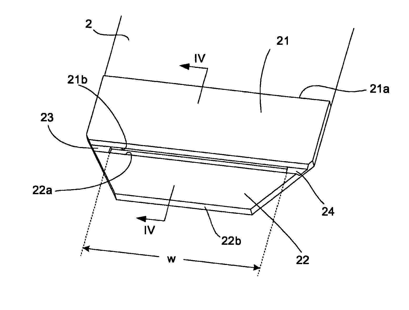
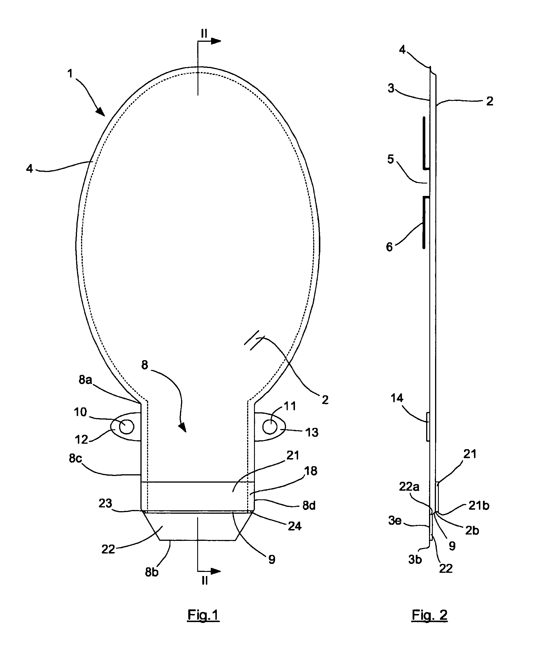
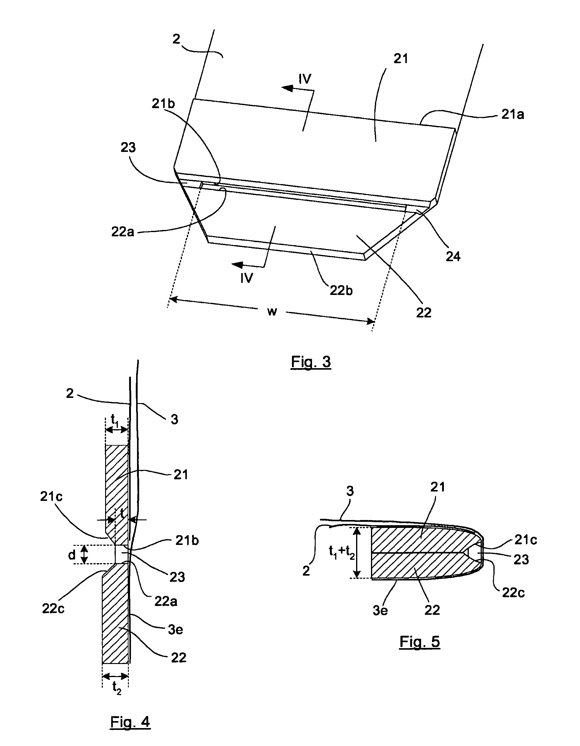
[0035]In FIG. 2 some sectional areas are indicated by fully drawn lines in order not to impede the clear reading of the drawings.

[0036]The collecting bag shown in the drawings is designed as a reusable ostomy bag and comprises a bag member 1 and a discharge portion 8 having a discharge opening 9, through which the collecting bag may be emptied of its contents. The general principles relating to such an ostomy bag are well known and common. One example of an ostomy bag is, for instance, disclosed in Applicant's international published application No. WO 2004 / 030584.

[0037]The collecting bag may assume a number of different positions, depending on whether the bag is in its discharge position, in an intermediate position in which the bag is closed but not locked, in a position of use in which the bag is closed and locked, or in any other position. In FIGS. 1 and 2, the collecting bag assumes a position which will be referred to simply as “a first position”. This first position may for i...


PUM

PropertyMeasurementUnit
thicknessaaaaaaaaaa
distanceaaaaaaaaaa
thicknessaaaaaaaaaa

Abstract

The collecting bag is intended for human body wastes and has a bag member (1) and a discharge portion (8) including a discharge opening (9). The bag member (1) and the discharge portion (8) are formed by a first and a second film blank (2, 3). A first plate member (21) is positioned on the first film blank (2) and a second plate member (22) is positioned on an extension (3e) of the second film blank (3) such that the plate members have a distance (d) between them. Two strap members (23, 24) are positioned between the first and the second plate member (21, 22).

Description

[0001]This is a national stage of PCT / DK07 / 050041 filed Apr. 4, 2007 and published in English.FIELD OF THE INVENTION[0002]The invention relates to a collecting bag for human body wastes, comprising a bag member, and a discharge portion including a discharge opening and having a longitudinal direction, said bag member and said discharge portion being formed by a first and a second film blank, the second of said film blanks being provided with an extension in said discharge portion, said collecting bag furthermore including a first plate member having a distal edge and a second plate member having a proximal edge, said first plate member being positioned on the first film blank and said second plate member being positioned on the extension of the second film blank, said discharge opening extending between said facing edges, said collecting bag having a position, in which said first and second plate members are situated one after the other in the longitudinal direction of said discharg...

Claims


Application Information

Patent Timeline
Patent Type & Authority Patents(United States)
IPC IPC(8): A61M1/00A61F5/44B65D33/06B65D33/16
CPCA61F5/4407A61F5/445Y10T29/49826
Inventor SCHERTIGER, LARS OLAV
Owner COLOPLAST AS
Why Eureka
Try Eureka