Composite optical element and projection optical device

a technology of optical elements and projection devices, applied in the field of composite optical elements and projection optical devices, can solve the problems of preventing the system from being used as portable units, difficult to reduce the size of the optical system, and difficult to integrate those three optical elements into one unit, so as to improve the mechanical reliability and stability of the whole device, reduce the number of reflecting surfaces formed between the optical elements, and improve the mechanical reliability and stability. the effect of stability

Inactive Publication Date: 2012-07-24
SONY DEUT GMBH +1
View PDF24 Cites 0 Cited by
  • Summary
  • Abstract
  • Description
  • Claims
  • Application Information

AI Technical Summary

Benefits of technology

[0023]The projection optical device 21 shown in FIG. 5 also includes a plurality of optical elements including an element modifying the optical path, and therefore there are similar problems to those described above. In addition, it is desirable to improve efficiency in the use of light emitted from the light source, and to provide the whole device with a compact and robust structure.
[0024]There is a need for providing a composite optical element in which air gaps are not required, and the mechanical reliability and stability are improved.
[0025]In addition, it is desirable to provide a compact and robust projection optical device that includes the above-described composite optical element and has excellent efficiency in the use of light emitted from a light source.
[0028]According to an embodiment of the present invention, the composite optical element including the element modifying the optical path has no need to be provided with air gaps, and can be constructed as one integrated component. Accordingly, mechanical reliability and stability can be improved.
[0029]According to an embodiment of the present invention, the projection optical device includes the above-described composite optical element, and therefore mechanical reliability and stability of the whole device can be improved. In addition, since the number of reflecting surfaces formed between the optical elements can be reduced in comparison to the projection device of the related art having the air gap provided in between, there is provided the projection optical device which is excellent in using light emitted from the light source. Moreover, since a plurality of optical elements are bonded together with the low refractive index material layers in between, the projection optical device can be compact and robust.

Problems solved by technology

Therefore, it was difficult to integrate those three optical elements into one unit by bonding together, for example.
As a result, precise alignment of such optical systems 1 and 6 may be critical due to environmental causes such as shock, temperature change and the like, which prevents the systems from being used as portable units.
In addition, the optical systems 1 and 6 include the air gaps 11 and 12, respectively, and therefore it has been difficult to reduce the size of the optical systems.
Furthermore, it has been difficult to integrate a plurality of components into one unit, when considering the optical system formed of the plurality of optical elements including an element modifying the optical path to be a module.
Thus, there has been such a problem that the optical system of the related art is mechanically less reliable and stable.

Method used


Image

  • Composite optical element and projection optical device
  • Composite optical element and projection optical device
  • Composite optical element and projection optical device

Examples


Embodiment Construction

[0048]Hereinafter, preferred embodiments of the present invention are explained by referring to the accompanying drawings. It should be noted that the embodiments of the present invention are not limited to those described below, and it should be appreciated that various modifications and alterations can be effected arbitrarily without deviating from the scope and spirit of the present invention.

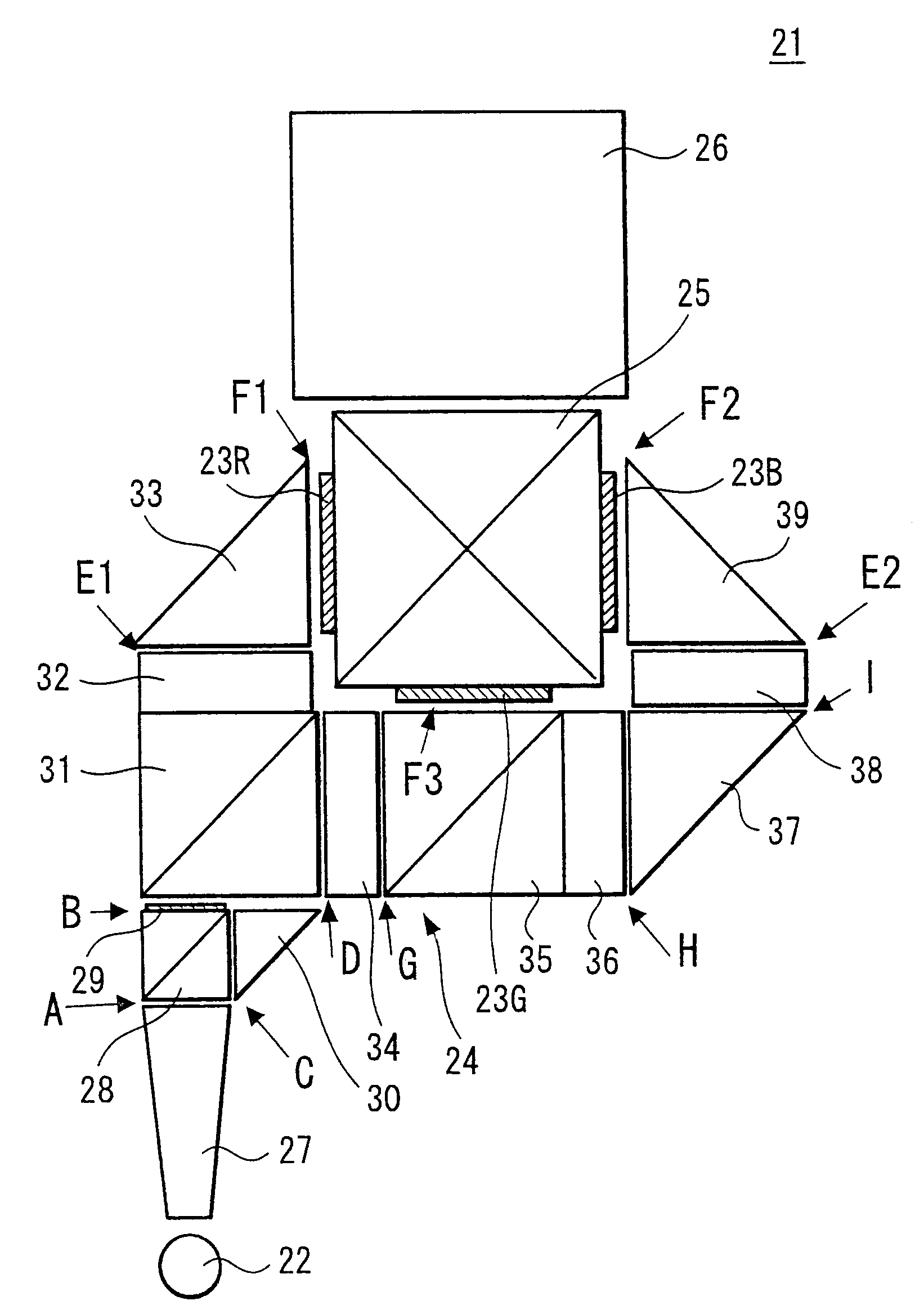
[0049]First, a composite optical element according to an embodiment of the present invention is explained. The composite optical element according to the embodiment is used for optical devices of various uses. For example, the composite optical element can also be used for a transmissive or reflective optical projector including: a light source, illumination optical system, transmissive panel or reflective panel (that is, light valve or image-forming light valve), and projection optical system (projection lens).

[0050]The composite optical element according to the embodiment includes a plural...


PUM


Abstract

A composite optical element is provided. The composite optical element includes a plurality of optical elements, in which at least one of the optical elements is formed of an element modifying an optical path and the other optical elements are bonded to an incident surface and / or exit surface of the element modifying the optical path with a low refractive index material layer in between.

Description

CROSS REFERENCES TO RELATED APPLICATIONS[0001]The present invention contains subject matter related to Japanese Patent Application JP 2006-114855 filed in the Japanese Patent Office on Apr. 18, 2006, the entire contents of which being incorporated herein by reference.BACKGROUND OF THE INVENTION[0002]1. Field of the Invention[0003]The present invention relates to a composite optical element including a plurality of optical elements in which at least one optical element is an element modifying an optical path.[0004]Further, the present invention relates to a projection optical device that includes the above-described composite optical element, and projects an image on a screen.[0005]2. Description of the Related Art[0006]US Patent Application Publication No 20050063196 A1 discloses an optical system including a combination of a plurality of optical elements such as a light pipe constituting a light guiding path and a prism bending an optical path, for example. The light pipe represent...

Claims


Application Information

Patent Timeline
Patent Type & Authority Patents(United States)
IPC IPC(8): G03B21/28
CPCG02B27/1046G02B27/145G02B27/149H04N9/3105H04N9/317H04N9/3197
Inventor UEDA, MITSUNORIOSHIMA, YOSHIHIROYAMAMOTO, KAZUTOSHITOYOTA, KIYOSHIWAJIKI, ATSUHIKOKATO, YUJIRIPOLL, OLIVIERTEIJIRO, JUAN MANUEL
Owner SONY DEUT GMBH
Why Eureka
Try Eureka