Backlight module and display device

a backlight module and display device technology, applied in lighting support devices, lighting and heating apparatus, instruments, etc., can solve the problems of increasing the cost of the backlight module, and achieve the effects of improving the brightness difference, improving the luminance uniformity of the backlight module, and improving the display quality of the display device using the backlight modul

Active Publication Date: 2012-08-07
AMTRAN TECH CO LTD
View PDF6 Cites 17 Cited by
  • Summary
  • Abstract
  • Description
  • Claims
  • Application Information

AI Technical Summary

Benefits of technology

[0009]The present invention is also directed to a display device with good display quality.
[0026]As described above, according to the present invention, the brightness of the first LED device is greater than that of the second LED device. Thus, the reflection ratio of the first reflection region in the reflection device opposite to the light-emitting energy of the first LED device is smaller than that of the second reflection region opposite to the light-emitting energy of the second LED device. As a result, the brighter first LED device receives less reflected light intensity while the darker second LED device receives more reflected light intensity, so that the brightness difference between the first LED device and the second LED device is reduced, the luminance uniformity of the backlight module is improved, and the display quality of a display device using the backlight module is also improved.

Problems solved by technology

However, the cost of the backlight module may be increased by purchasing a large number of LEDs having similar brightness.

Method used


Image

  • Backlight module and display device
  • Backlight module and display device
  • Backlight module and display device

Examples


Embodiment Construction

[0034]Reference will now be made in detail to the present preferred embodiments of the invention, examples of which are illustrated in the accompanying drawings. Wherever possible, the same reference numbers are used in the drawings and the description to refer to the same or like parts.

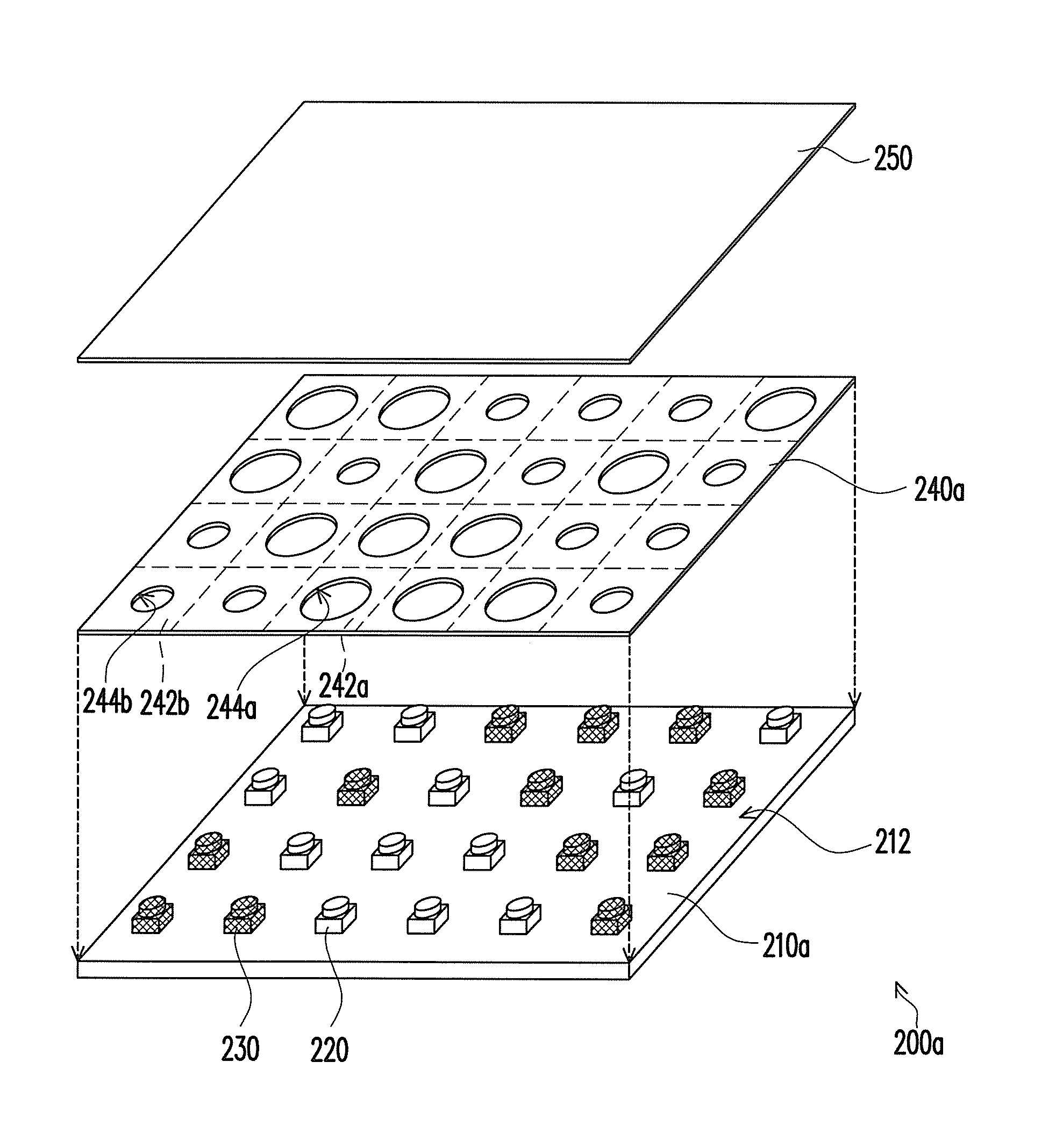
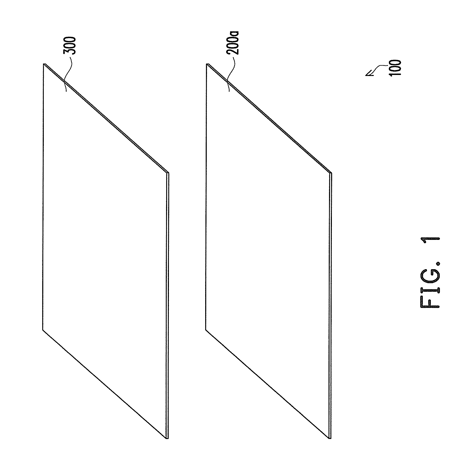
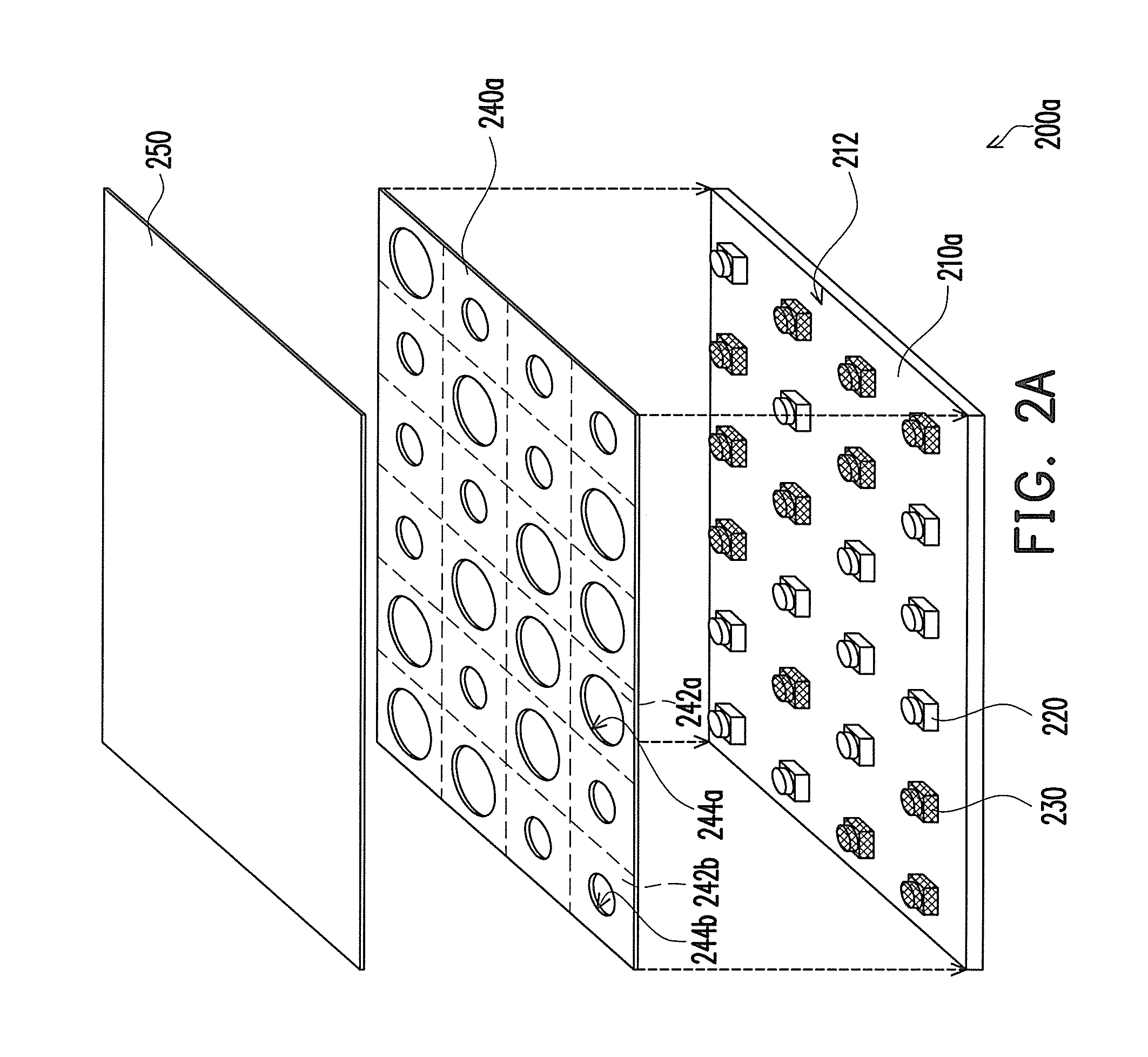
[0035]FIG. 1 is a diagram of a display device according to an embodiment of the present invention, FIG. 2A is an explosion diagram of a backlight module in FIG. 1, and FIG. 2B is a comprehensive diagram of the backlight module in FIG. 2A. Referring to both FIG. 1 and FIG. 2A, in the present embodiment, the display device 100 includes a backlight module 200a and a display panel 300, wherein the backlight module 200a is disposed at one side of the display panel 300 (for example, below the display panel 300) for providing a display light source to the display panel 300. The display device 100 may be a liquid crystal display (LCD) device.

[0036]In the present embodiment, the backlight module 200a includes...


PUM


Abstract

A backlight module including a circuit board, at least one first light emitting diode (LED) device, at least one second LED device, and a reflection device is provided. The first and second LED devices are disposed on a carrying surface of the circuit board and electrically connected to the circuit board. The brightness of the first LED device is greater than that of the second LED device. The reflection device is disposed on the circuit board and exposes the first and second LED devices. The reflection device has at least one first reflection region disposed around the first LED device and at least one second reflection region disposed around the second LED device. The reflection ratio of the first reflection region opposite to the light-emitting energy of the first LED device is smaller than that of the second reflection region opposite to the light-emitting energy of the second LED device.

Description

CROSS-REFERENCE TO RELATED APPLICATION[0001]This application claims the priority benefit of Taiwan application serial no. 98127890, filed Aug. 19, 2009. The entirety of the above-mentioned patent application is hereby incorporated by reference herein and made a part of specification.BACKGROUND OF THE INVENTION[0002]1. Field of the Invention[0003]The present invention generally relates to a light source module and a display device, and more particularly, to a backlight module and a display device using the same.[0004]2. Description of Related Art[0005]Along with the development of electronic technology, flat panel display has gradually replaced the conventional cathode ray tube (CRT) display as the mainstream display. Among all the existing flat panel displays, liquid crystal display (LCD) has the most mature technique and is most broadly used. Because the panel of a LCD does not emit light itself, a backlight module has to be provided as a display light source of the panel.[0006]Amo...

Claims


Application Information

Patent Timeline
Patent Type & Authority Patents(United States)
IPC IPC(8): G09F13/04F21S4/00
CPCG02F1/133603G02F1/133605G02F1/133611
Inventor CHEN, CHIEN-CHOU
Owner AMTRAN TECH CO LTD
Why Eureka
Try Eureka