Multi-loop antenna module with wide beamwidth

a technology of antenna modules and beamwidth, applied in the structural form of loop antennas, antenna earthings, radiating elements, etc., can solve the problems of deteriorating the aesthetic appeal of products, increasing costs, and affecting the performance of whole systems, and achieves good isolation, small size, and low profile.

Active Publication Date: 2012-09-18
LITE ON ELECTRONICS (GUANGZHOU) LTD +1
View PDF2 Cites 5 Cited by
  • Summary
  • Abstract
  • Description
  • Claims
  • Application Information

AI Technical Summary

Benefits of technology

[0008]In view of the aforementioned issues, the present invention provides a multi-loop antenna module with wide beamwidth. The present invention not only has some advantages such as small size, low profile, good isolation, good radiation properties and extensive application field (for example may be arbitrarily installed on a ceiling, wall or table), but also can replace the external dual-band single-radio access-point antenna of the prior art for 2.4 / 5 GHz operation with no need of extra diplexers. In addition, the built-in multi-loop antenna module may be hidden in the access-point or router in order to enhance the appearance of the product.

Problems solved by technology

However, the protruded part of the dipole antenna can easily be vandalized by an outside force and also occupies space, which deteriorates the aesthetic appeal of the product, especially for the multi-antenna system.
However, the typical dual-band antenna needs a diplexer to simultaneously transmit and / or receive the 2.4 GHz and 5 GHz band signals to a 2.4 GHz module or a 5 GHz module, so that the cost would be increased, and the whole system loses extra gain or power.
However, radiation patterns generated by general antenna can only provide particular coverage, for example, a monopole antenna can only generate omnidirectional radiation patterns along a horizontal direction or conical radiation patterns along an elevation direction, and a patch or microstrip antenna can only provide broadside radiation patterns.
In other words, if the access-point antenna is applied to a ceiling, the user cannot take the ceiling-mount access-point antenna for a wall mount access point.
It is obvious that the access-point antenna generates different antenna radiation patterns and directions, according to different applications, so that the access-point antenna of the related art, if applied to a wrong place, will generate a communications dead zone to decrease RF signal receiving efficiency and signal transmitting quality.

Method used


Image

  • Multi-loop antenna module with wide beamwidth
  • Multi-loop antenna module with wide beamwidth
  • Multi-loop antenna module with wide beamwidth

Examples


Embodiment Construction

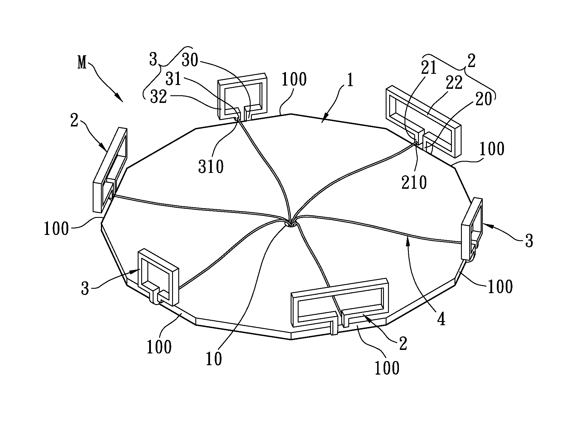
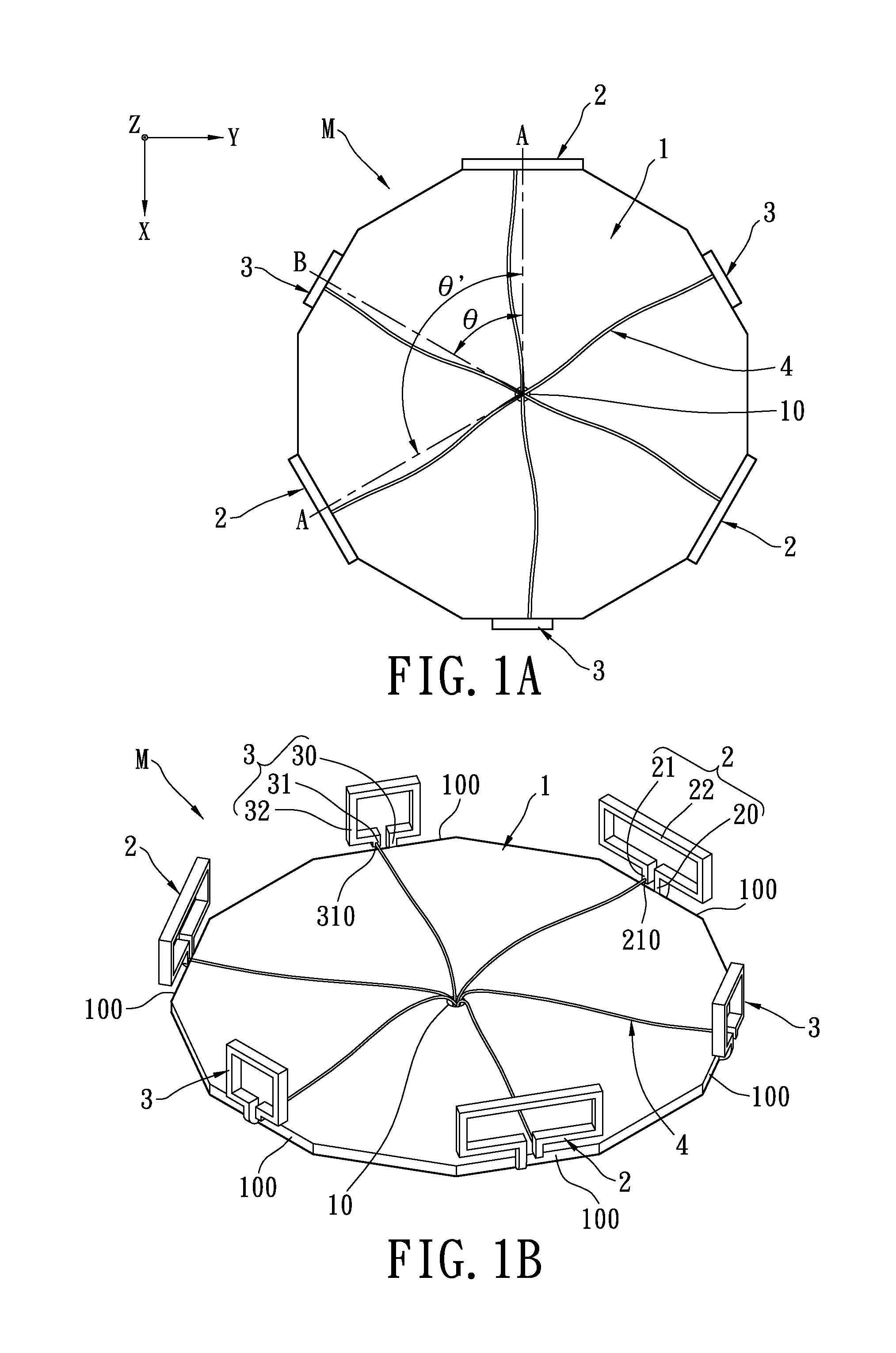
[0028]Referring to 1A to 1D, the first embodiment of the present invention provides a multi-loop antenna module M with wide beamwidth, including: a grounding unit 1, a plurality of first loop units 2 and a plurality of second loop units 3. The first loop units 2 and the second loop units 3 are alternately and symmetrically arranged around a geometric center of the grounding unit 1 and vertically disposed on the grounding unit 1. In addition, the grounding unit 1, the first loop units 2 and the second loop units 3 may be integrally combined to form one-piece metal plate. Of course, the grounding unit 1, the first loop units 2 and the second loop units 3 may be manufactured respectively, and then the finished first loop units 2 and the finished second loop units 3 are disposed on the finished grounding unit 1.

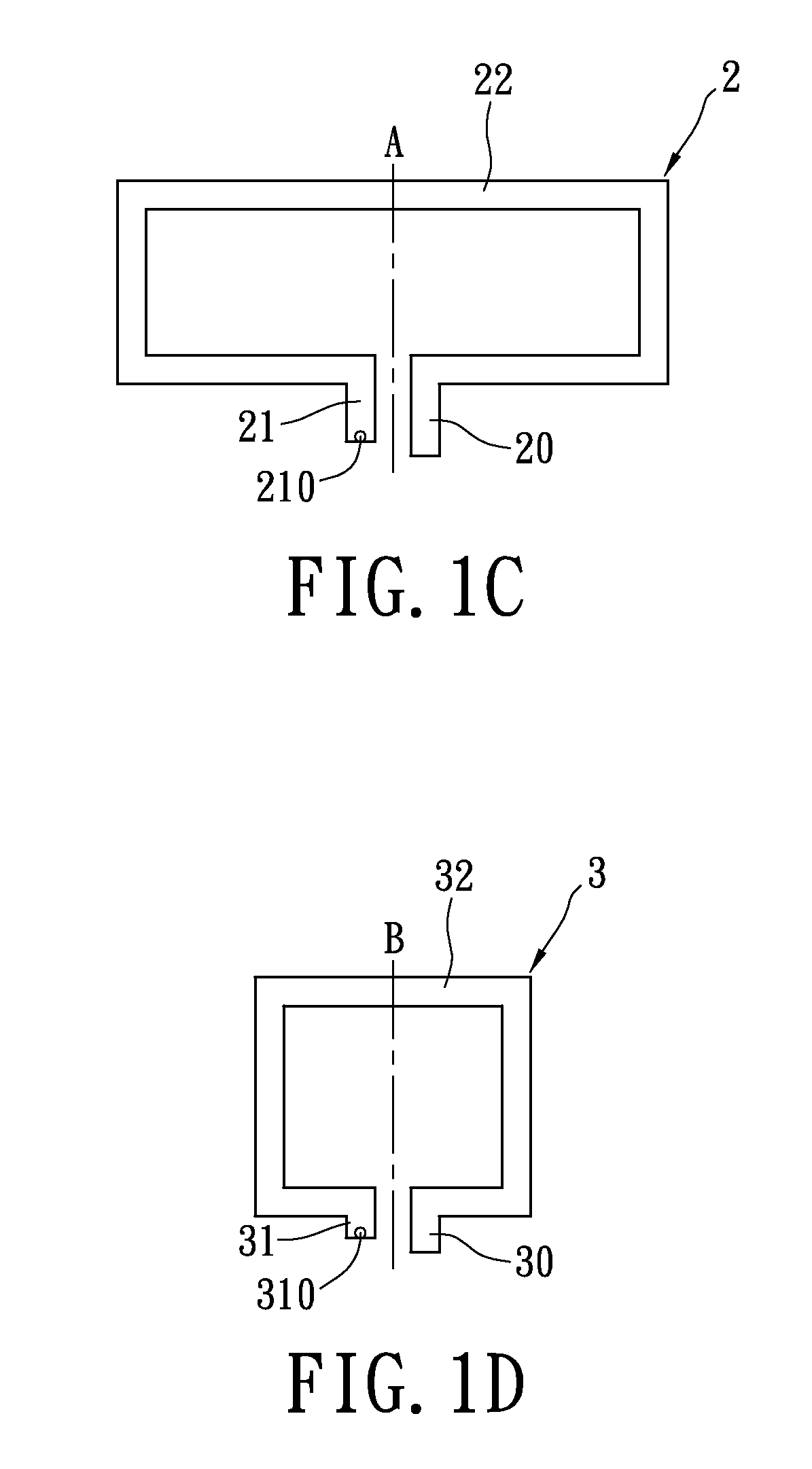
[0029]The first loop units 2 and the second loop units 3 are alternately and symmetrically arranged on the grounding unit 1. Each first loop unit 2 has a geometric centerline A (...


PUM


Abstract

A multi-loop antenna module with wide beamwidth includes a grounding unit and a plurality of first loop units and second loop units. The first loop units are vertically disposed on outer peripheral sides of the grounding unit. Each first loop unit has a first shorting pin disposed on the grounding unit, a first feeding pin separated from the first shorting pin and suspended above the grounding unit, and a first loop radiating body connected between the first shorting pin and the first feeding pin. The second loop units are vertically disposed on outer peripheral sides of the grounding unit. Each second loop unit has a second shorting pin disposed on the grounding unit, a second feeding pin separated from the second shorting pin and suspended above the grounding unit, and a second loop radiating body connected between the second shorting pin and the second feeding pin.

Description

BACKGROUND OF THE INVENTION[0001]1. Field of the Invention[0002]The present invention relates to a multi-loop antenna module, in particular, to a multi-loop antenna module with wide beamwidth for providing good RF communications coverage.[0003]2. Description of Related Art[0004]The wireless LAN or 802.11a / b / g / n access-point antenna of the related art is almost of an external antenna structure. Common dipole antennas have a plastic or rubber sleeve covering thereon. In general, the dipole antenna is a single-band antenna for 2.4 GHz operation or a dual-band antenna for 2.4 / 5 GHz operation. The height of the dipole antenna is triple the thickness of the wireless broadband router / hub device, and one part of the dipole antenna is disposed on a side of the router and the rest of the dipole antenna is protruding from the top of the access-point or router housing. However, the protruded part of the dipole antenna can easily be vandalized by an outside force and also occupies space, which d...

Claims


Application Information

Patent Timeline
Patent Type & Authority Patents(United States)
IPC IPC(8): H01Q11/12
CPCH01Q1/36H01Q21/205H01Q7/00
Inventor SU, SAOU-WEN
Owner LITE ON ELECTRONICS (GUANGZHOU) LTD
Why Eureka
Try Eureka