A cassegrain antenna

A Cassegrain antenna and antenna technology, applied in the direction of antenna, antenna grounding switch structure connection, waveguide horn, etc., can solve the problems of narrow beam and target loss

Active Publication Date: 2021-07-09
NANJING UNIV OF AERONAUTICS & ASTRONAUTICS
View PDF3 Cites 0 Cited by
  • Summary
  • Abstract
  • Description
  • Claims
  • Application Information

AI Technical Summary

Problems solved by technology

But traditional Cassegrain antennas have a narrow beam across the frequency band, and slight offsets can cause target loss

Method used


Image

  • A cassegrain antenna
  • A cassegrain antenna
  • A cassegrain antenna

Examples


Embodiment 1

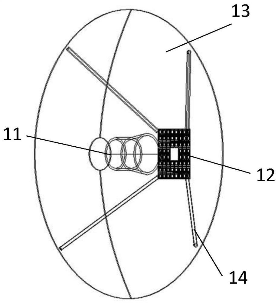
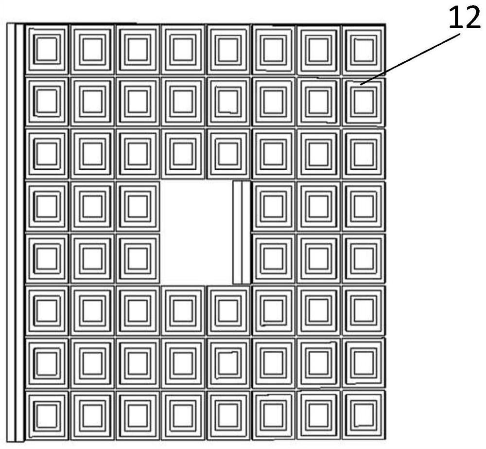
[0030] Embodiment 1, a Cassegrain antenna, comprising a feed antenna 11, a main reflector 13, a secondary reflector 12, and a main and secondary reflector fixing device 14; the feed antenna 11 is a conical horn in a horn antenna, The main reflector 13 is in the form of a paraboloid, and the secondary reflector 12 is a frequency selective surface with a side length of 4-7mm square holes at the center, such as figure 1 As shown, the frequency selective surface can generate resonance at some specific frequency points, so that the electromagnetic wave at this frequency point is transmitted, resulting in a wider beam width, while it is reflected at other frequency points, and the beam width narrower.

[0031] The feed antenna 11 is a conical horn, a kind of horn antenna. The feeding structure of the conical horn includes a hollow cone with a base radius of 10 mm and a height of 8-10 mm. Round tube waveguide. The structure is simple, the feeding method is simple, it has a moderate...

Embodiment 2

[0035] Embodiment 2, the frequency selective surface 15 in the embodiment 1 is composed of the frequency selective surface 15, and the inclination angle is 8-12°, such as Figure 6 As shown, the incident angle of the electromagnetic wave has a certain change, but it has little effect on its transmission characteristics, and its reflection characteristics change the direction of the reflected wave due to the change of the angle, and the reflected wave received by the feed antenna is small, effectively improving Standing wave characteristics; the electromagnetic wave is radiated from the conical horn 11 to the sub-reflecting surface, because the sub-reflecting surface has a certain angle to the incident wave, so the vertical reflection of the electromagnetic wave can be avoided, and the return loss of the antenna can be reduced to less than - 18dB effect.

Embodiment 3

[0036] In Embodiment 3, the frequency selective surface 15 described in Embodiment 1 is composed of a hyperboloid secondary reflection surface, such as Figure 7 As shown, the improvement according to the geometric principle can achieve the effect of reducing the return loss of the antenna to less than -17dB.


PUM


Abstract

A Cassegrain antenna, comprising a feed antenna (11), a main reflector (13), a secondary reflector, and a fixing device (14) for the main and secondary reflectors; the feed antenna (11) is a horn antenna Conical horn, the main reflection surface (13) is in the form of a paraboloid, and the secondary reflection surface is replaced by a frequency selective surface (15), which can generate resonance at the frequency points of 8-14.5GHz and 29-34GHz, so that The electromagnetic wave at this frequency point is transmitted, resulting in a wider radiation pattern, while at other frequency points it is reflected, and the pattern is narrower, which greatly improves the performance of the mobile communication system, and the antenna is dual-frequency. , and its working frequency bands are 8-14.5GHz and 29-34GHz respectively. In the two working frequency bands, its pattern contains a radiation pattern with a narrow beam and a wide beam respectively, which can be well applied to mobile communication antennas system.

Description

technical field [0001] The invention relates to an antenna. Background technique [0002] With the development of satellite communication, mobile communication equipment has extremely important applications in various occasions such as media on-site interviews. The so-called mobile communication system is the abbreviation of "moving satellite ground station communication system". Pointing to the direction of the satellite in real time, this process requires a servo system. The mobile communication antenna needs to have a narrow beam width and a large gain, and the Cassegrain antenna is a kind that can well meet its needs. But conventional Cassegrain antennas have a narrow beam across the frequency band, and slight offsets can cause target loss. Contents of the invention [0003] In view of the above prior art, the technical problem to be solved by the present invention is to provide a Cassegrain antenna capable of generating a wider beam width. [0004] In order to sol...

Claims


Application Information

Patent Timeline
Patent Type & Authority Patents(China)
IPC IPC(8): H01Q13/02H01Q19/19H01Q15/00H01Q1/50
CPCH01Q1/50H01Q13/02H01Q15/0026H01Q19/19
Inventor 刘可
Owner NANJING UNIV OF AERONAUTICS & ASTRONAUTICS
Why Eureka
Try Eureka