Antenna network for passive and active signal enhancement

a technology of passive or active enhancement and antenna network, which is applied in the direction of transmission monitoring, frequency-division multiplex, repeater/relay circuit, etc., can solve the problems of reducing the strength of signals transmitted and received in electronic devices through the em shield, compromising the transmission or reception of signals, etc., to minimise the formation of current loops and minimise feedback

Active Publication Date: 2012-10-30
CONVENIENTPOWER HK
View PDF23 Cites 44 Cited by
  • Summary
  • Abstract
  • Description
  • Claims
  • Application Information

AI Technical Summary

Benefits of technology

[0012]Preferably, the antenna network has a plurality of the antennas spaced apart such that interference between the antennas is minimised.
[0017]In a further embodiment, the array of linear strips is aligned in a first direction, and one or more of the coupling portions of the one or more antennas form another array of spaced substantially parallel linear strips aligned in a second direction across the coupling area, thereby forming a matrix of linear strips across the coupling area. Preferably, the arrays of linear strips are electrically isolated to minimise the formation of current loops. Also preferably, the first and second directions are substantially orthogonal to each other, thereby forming a grid of linear strips across the coupling area.
[0018]Preferably, at least one of the antennas includes an amplifying repeater connected between the coupling portion and the radiating portion for amplifying signal transmission or reception. Preferably, the amplifying repeater includes a power amplifier or a low noise amplifier. Also preferably, the amplifying repeater includes a mixer and a signal generator to change the frequency channel of signal transmission or reception, thereby to minimise any feedback. Preferably, the mixer includes a filter. Preferably, the signal generator includes a filter. Also preferably, the antenna includes a filter connected between the coupling portion and the amplifying repeater. It is also preferred that the antenna includes a filter connected between the radiating portion and the amplifying repeater.

Problems solved by technology

However, there are situations in which the signal transmission or reception of these devices is compromised.
Firstly, the presence of the EM shield shown in FIG. 1 substantially reduces the strength of the signals transmitted and received in the electronic devices through the EM shield.

Method used


Image

  • Antenna network for passive and active signal enhancement
  • Antenna network for passive and active signal enhancement
  • Antenna network for passive and active signal enhancement

Examples


Embodiment Construction

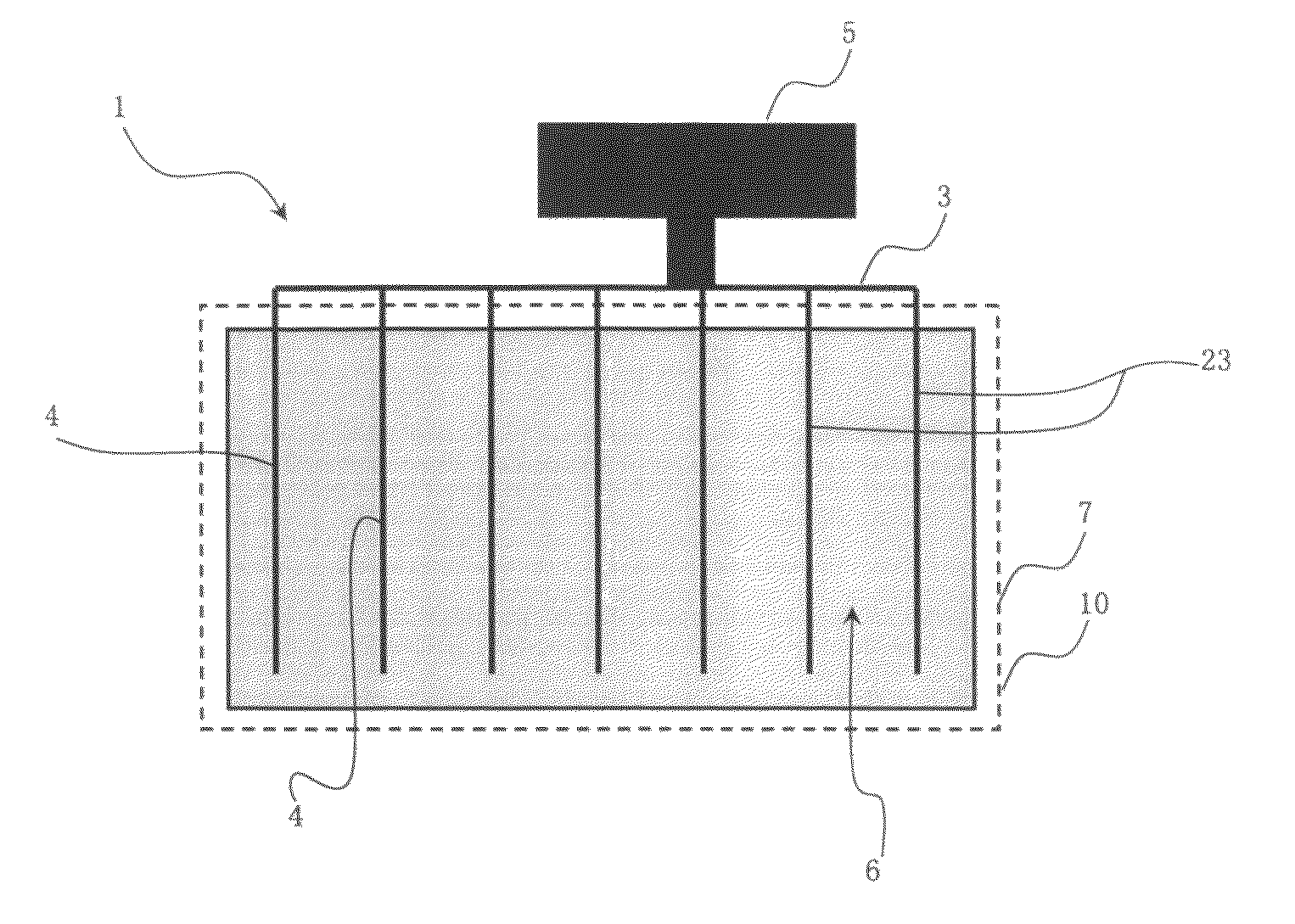
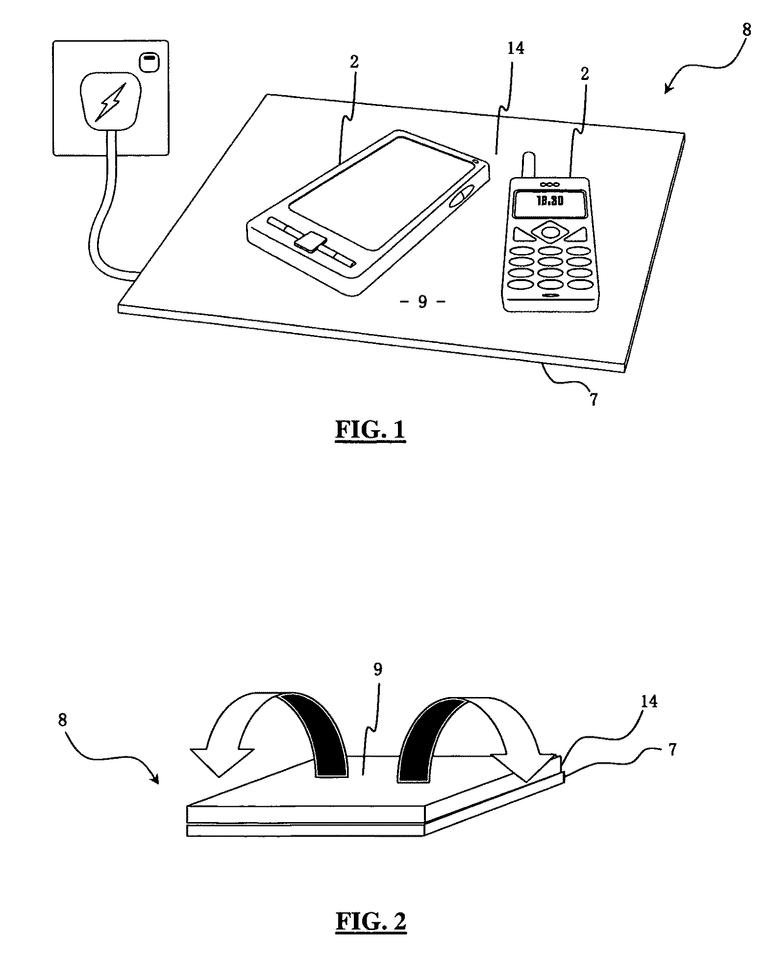
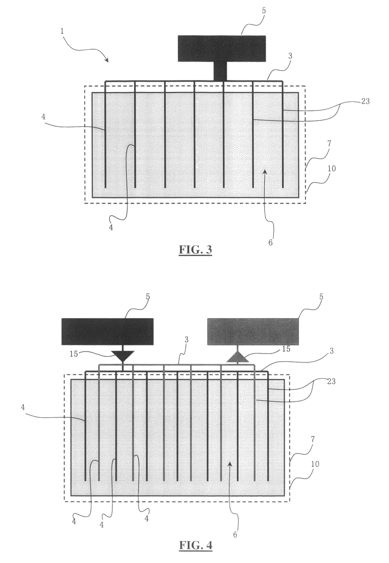
[0052]Referring to the figures, an antenna network 1 for enhancing signal transmission or reception of one or more portable transceiver devices 2 is provided. The antenna network 1 includes one or more antennas 3, each having a coupling portion 4 and a radiating portion 5. The coupling portion 4 is distributed across a coupling area 6 and the radiating portion 5 is located away from the coupling area 6, whereby signal transmission or reception of the one or more portable transceiver devices 2 can occur through the radiating portion 5 when the one or more portable transceiver devices are located within the coupling area 6.

[0053]Thus, signal transmission or reception of the portable transceiver devices 2 is enhanced. In general, this is achieved by allowing signal transmission or reception in many directions by using the radiating portion or portions 5, especially those directions in which signal transmission or reception of the portable transceiver devices 2 would otherwise be weak i...


PUM


Abstract

The Present Invention Provides an Antenna Network for Passively or Actively enhancing signal transmission or reception of one or more portable transceiver devices. The antenna network includes one or more antennas, each having a coupling portion and a radiating portion, the coupling portion being distributed across a coupling area and the radiating portion being located away from the coupling area, whereby signal transmission or reception of the one or more portable transceiver devices can occur through the radiating portion when the one or more portable transceiver devices are located within the coupling area.

Description

FIELD OF THE INVENTION[0001]The present invention relates to antenna networks for passive or active enhancement of signal transmission or reception. The invention has been described in relation to the enhancement of signal transmission and reception of portable transceiver devices in the context of use with wireless power transfer devices, but it will be appreciated that the invention is not limited to this particular application.BACKGROUND OF THE INVENTION[0002]There is a wide variety of portable transceiver devices, that is, devices capable of signal transmission or reception, for use in many applications. For example, mobile phones and most netbook computers have inbuilt antennas for transmitting and receiving signals for wireless communication. However, there are situations in which the signal transmission or reception of these devices is compromised.[0003]One situation is when portable transceiver devices are being charged by wireless power transfer devices. Recent developments...

Claims


Application Information

Patent Timeline
Patent Type & Authority Patents(United States)
IPC IPC(8): H04B3/36
CPCH04B5/0037H01Q1/242
Inventor XUE, QUANHUI, SHU YUEN RONWAN, KWUN CHIU
Owner CONVENIENTPOWER HK
Why Eureka
Try Eureka