Electrical connector

a technology of electrical connectors and connectors, applied in the direction of coupling device connections, connection contact member materials, coupling protective earth/shielding arrangements, etc., can solve the problems of insufficient distance between the two terminals of each differential signal terminal pair, and conventional technology is not suitable for adaptation, so as to reduce the interference between the terminals and simplify the structure

Active Publication Date: 2010-03-09
MOLEX INC
View PDF16 Cites 43 Cited by
  • Summary
  • Abstract
  • Description
  • Claims
  • Application Information

AI Technical Summary

Benefits of technology

[0006]An electrical connector has a terminal arrangement which allows the distance between adjacent sets of differential signal pairs to be increased at the mounting end of the connector. The interference between the adjacent sets of differential signal pairs can be reduced, and the size of the entire electrical connector need not be increased despite such improvements.
[0007]The electrical connector provides an electrical connector comprising an insulating body, a plurality of signal terminals and a plurality of grounds terminals, both contained in the insulating body. Each of the signal terminals and ground terminals comprises a contact portion, a foot portion and a connection portion connecting the contact portion to the foot portion. The contact portions of the terminals are arranged in two lines on the insulating body, with the foot portions are also arranged in two lines. The location arrangement of the free ends of the foot portions of the signal terminals and ground terminals included in one line correspond with the location arrangement of their contact portions. Compared with the free ends of the foot portions of each signal terminal pair in the line, the distance between the free ends of the foot portions of two corresponding adjacent terminals in the other line is increased.
[0009]Compared with the conventional electrical connector having foot portions arranged in three lines, the present electrical connector features both contact portions and foot portions arranged in two lines. The arranged sequence of the terminals is identical to each other for the two lines. The pitches of the foot portions of one line are varied within a certain segment. Therefore, the interference between the terminal can be reduced, and the structure is simplified so that the electrical connector is suitable for miniaturized electrical products.

Problems solved by technology

Therefore, the distance between the two terminals of each differential signal terminal pair is not sufficient to reduce interference from occurring between the pair of differential signals applied to the differential signal terminal pair.
Consequentially, such conventional technology is not suitable to be adapted to current electrical products that follow the current miniaturization trend.

Method used


Image

  • Electrical connector
  • Electrical connector
  • Electrical connector

Examples


Embodiment Construction

[0021]While the invention may be susceptible to embodiment in different forms, there is shown in the drawings, and herein will be described in detail, a preferred embodiment with the understanding that the present disclosure is to be considered an exemplification of the principles of the invention, and is not intended to limit the invention to that as illustrated and described herein.

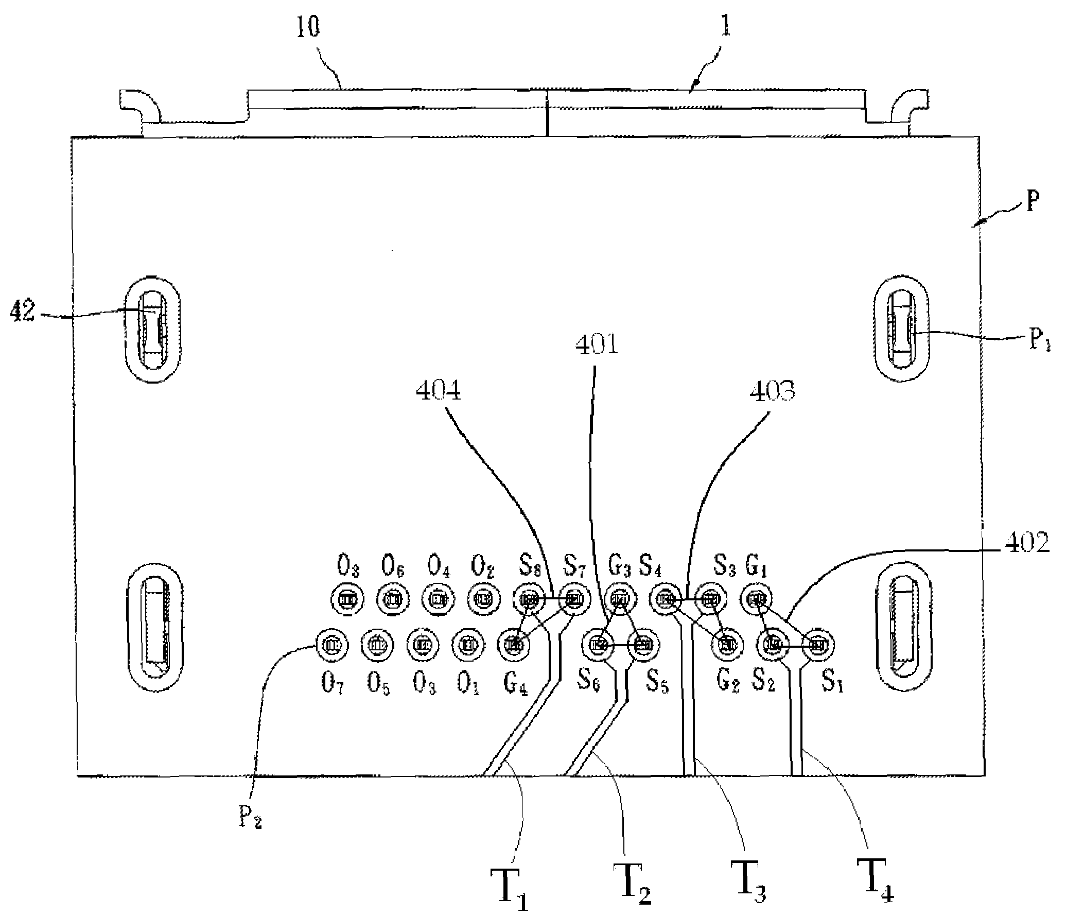
[0022]FIG. 3 illustrates an electrical connector 1 for transmitting differential signals at high speeds. The connector 1 includes an insulative housing, or body 2, a plurality of terminals 3 contained in the insulating body 2 and a cover 4 shielding the insulative body 2. The connector 1 is mounted on a circuit board P, and allows a counterpart mating connector (not shown) to connect with the connector 1 so that the high-speed differential signals can be transmitted therein. The side of the connector 1 facing the mating connector is hereinafter called a connection or mating side 10, the side opposite th...


PUM


Abstract

An electrical connector includes an insulating body and a plurality of signal terminals and ground terminals contained therein. Each terminal includes a contact portion, a foot portion and a connection portion therebetween. The contact portions are arranged in two lines on the insulating body, and the foot portions are arranged in two lines. The locations of the free ends of the foot portions included in one line correspond with the location arrangement of their contact portions. Compared with the free ends of the foot portions of each signal terminal pair in the line, the distance between the free ends of the foot portions of two corresponding adjacent terminals in the other line is increased.

Description

BACKGROUND OF THE INVENTION[0001]This application claims priority to PRC (China) Application No 200720194819.1, filed Oct. 25, 2007.[0002]The present invention relates generally to an electrical connector, and more particularly to an electrical connector for transmitting high speed differential signals.[0003]The conventional electrical connector for transmitting high speed differential signals has broad applications in the communications field, and some of these applications are disclosed by U.S. Pat. Nos. 7,090,540 and 7,077,668. FIGS. 1 and 2, which are drawings from U.S. Pat. No. 7,077,668, provide an electrical connector 6 comprising an insulating body 60, a plurality of terminals 61 contained in the insulating body 60, and a cover 62 shielding the insulating body 60. The insulating body 60 has a connection portion 600 and a plurality of terminal containing slots respectively containing the terminals 61 and passing through the connection portion 600. The terminals 61 comprise si...

Claims


Application Information

Patent Timeline
Patent Type & Authority Patents(United States)
IPC IPC(8): H01R13/648
CPCH01R24/60H01R13/6471H01R13/6477H01R12/725H01R2107/00H01R13/648H01R24/20H01R24/76
Inventor HE, HUA
Owner MOLEX INC
Why Eureka
Try Eureka