Central tire inflation wheel assembly and valve

a technology of tire inflation wheel and valve body, which is applied in the direction of functional valve types, valve housings, water supply installation, etc., can solve the problems of valve failure, valves can easily be damaged, and the valves are easy to fail, so as to increase improve the longevity of the valve, and simplify the valve construction

Active Publication Date: 2012-11-13
GLOBAL ENG MARKETING
View PDF22 Cites 19 Cited by
  • Summary
  • Abstract
  • Description
  • Claims
  • Application Information

AI Technical Summary

Benefits of technology

[0009]According to one aspect of the present invention, a tire valve is provided that can be seated directly on or within a tire wheel and includes a minimum of moving parts to simplify the construction of the valve and to increase the longevity of the valve. The valve includes a casing that is secured to the wheel rim to position the valve on the exterior of the rim or in a position where the valve is located in a recessed position with regard to the rim. The casing encloses a main body that is positioned within the casing in a sealed configuration to prevent air flow between the casing and the main body. The casing also includes an aperture that positions the main body in communication with an air supply used to inflate the tires of a vehicle such that the air supply can direct an air flow through the main body to the tire though an outlet in the casing. To control the air flow from the air supply, the main body includes a valve poppet sealingly, but movably secured therein, that includes a lower portion that is completely held within the main body, and an upper portion that extends outwardly from the main body. The upper portion includes a sealing member that selectively closes off the interior of the main body, to allow air flow from the air supply out of the main body past the valve poppet. The valve poppet is biased into a either an open or a closed position by a biasing member engaged between the valve poppet and the main body. The biasing member assists in enabling the valve poppet to be moved with regard to the main body with only slight changes in air pressure within the main body to allow air flow either to or from the tire. This allows the valve poppet to be operated very quickly and easily, such that control of the operation of the valve can be remotely controlled via a controller connected to the pressurized air source.
[0010]According to another aspect of the present invention, the valve poppet and biasing member of the valve are designed to be removably and replaceably positioned within either of two versions of the valve. Depending upon the particular application of the valve, i.e., the vehicle on which the valve is to be mounted, the valve poppet and biasing member can be inserted within the main body of the valve for controlling the air flow through the valve to the wheel rim. This design for the valve allows the valve to be quickly repaired or replaced should either of these components of the valve become damaged.

Problems solved by technology

These additional components greatly increase the cost and complexity of the valves and the associated CTIS, causing the valves to fail on a regular basis, necessitating that the valves be repaired and / or replaced on a consistent basis.
This positioning for the valve on the exterior of the rim in an exposed location where the valve can easily be damaged by debris or other objects striking the valve when the vehicle is in operation.

Method used


Image

  • Central tire inflation wheel assembly and valve
  • Central tire inflation wheel assembly and valve
  • Central tire inflation wheel assembly and valve

Examples


first embodiment

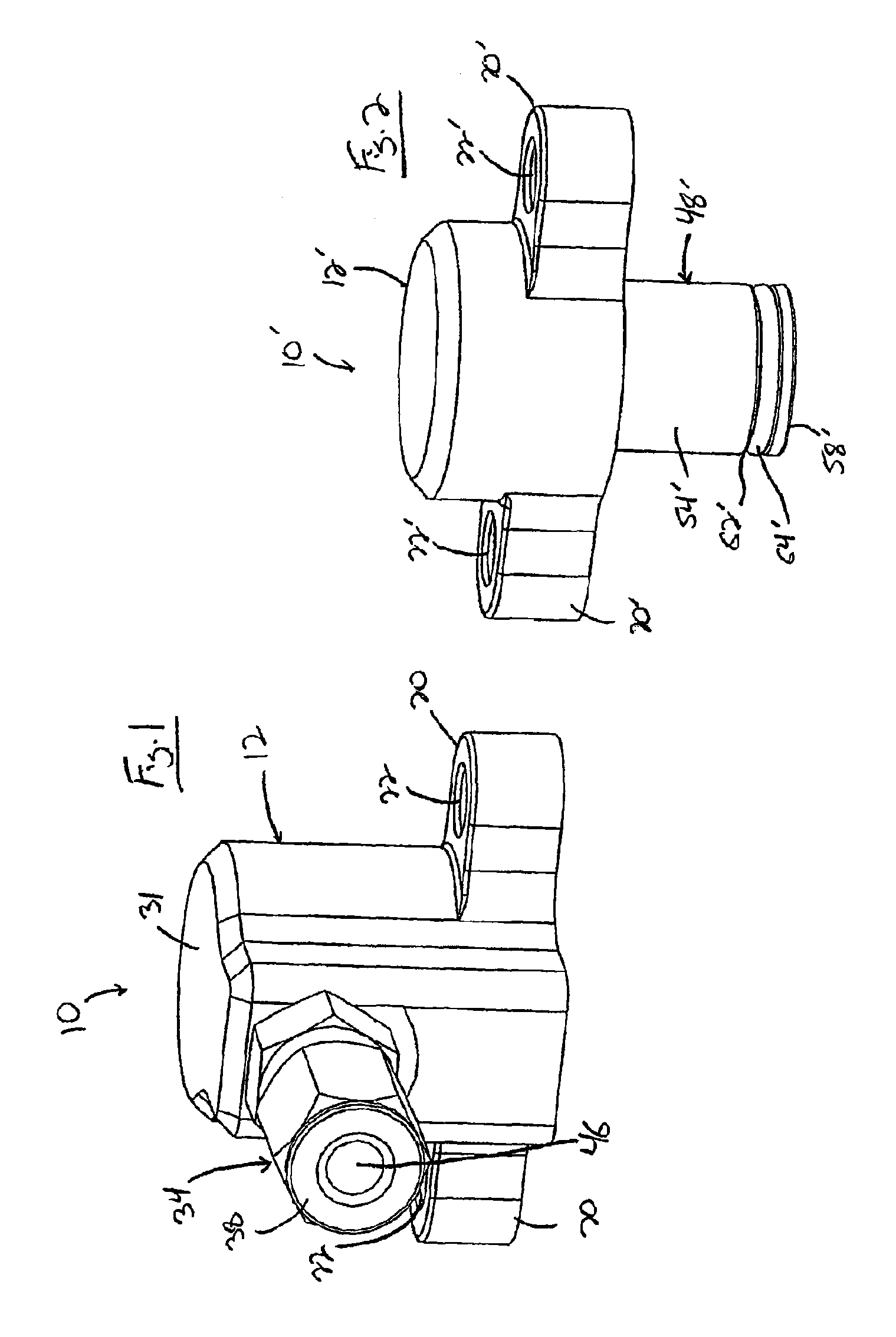
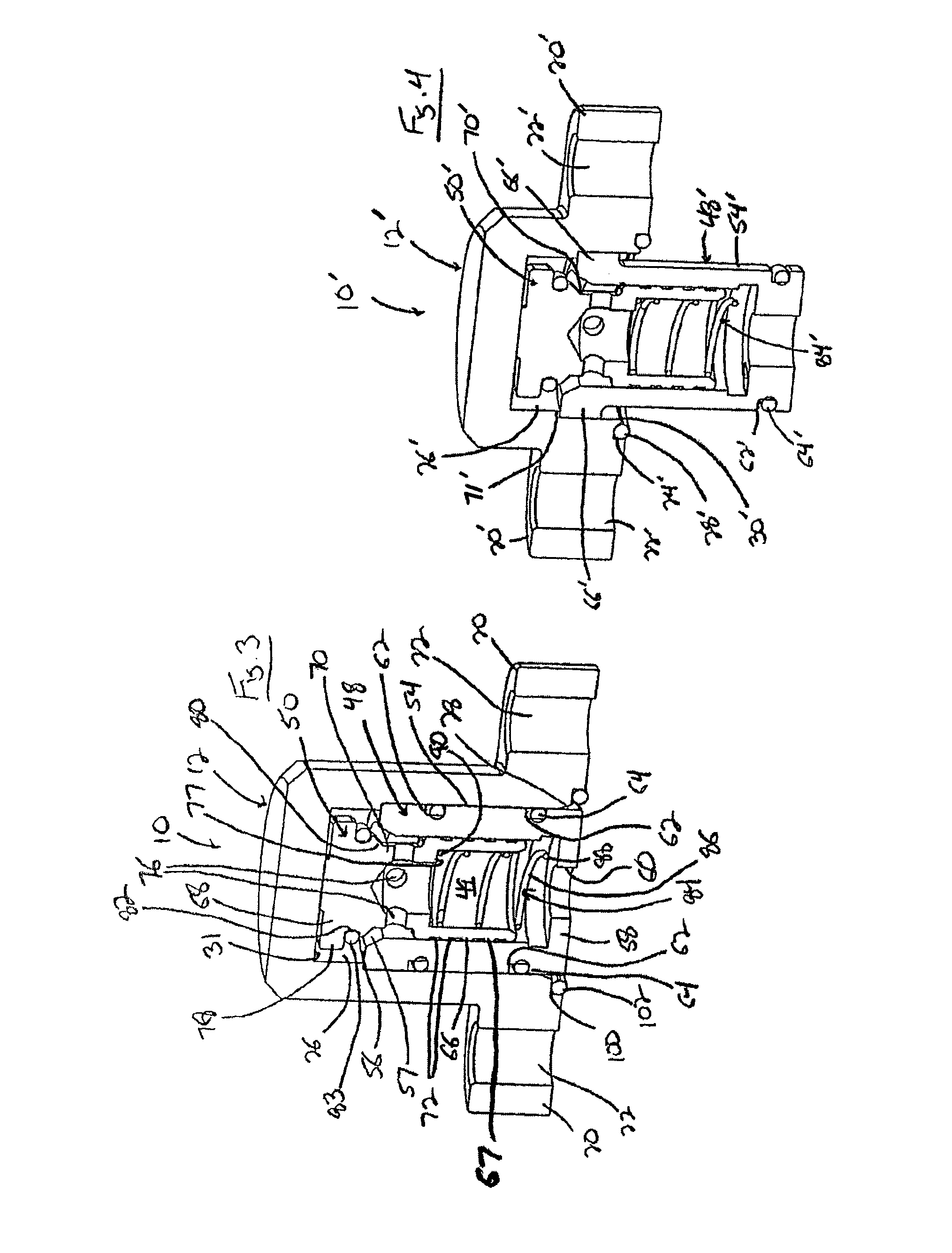
[0036]With reference now to the drawing figures in which like reference numerals designate like parts throughout the disclosure, a wheel valve constructed according to the present invention is indicted at 10 in FIGS. 1, 3 and 5-7. The valve 10 includes a casing 12 that is secured to the rim 14 of a wheel 16 adapted to support a tire (not shown) thereon. The rim 14 includes a number of air passages or channels 18 formed therein, with the casing 12 mounted over or otherwise in communication with one of the passages 18. The casing 12 is mounted flush against the rim 14 in any suitable manner to maintain an air-tight engagement between the casing 12 and the rim 14. In a preferred embodiment, the casing 12 includes a pair of flanges 20 extending outwardly from the casing 12 that include bores 22 formed therein. The bores 22 receive suitable fasteners 23 therethrough that are engaged with the rim 14 to affix the casing 12 to the rim 14. In a preferred embodiment, the flanges 20 are integr...

second embodiment

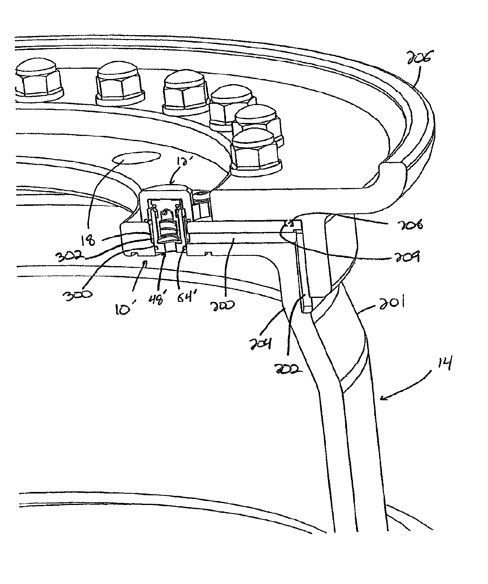
[0046]Looking now at FIGS. 2, 4, and 8-11, the valve 10′ is illustrated. In this embodiment, the valve 10′, instead of being mounted flush with the rim 14, as for valve 10, is mounted within the passage 18, such that the valve 10′ is recessed within the rim 14 to lessen exposed portion of the valve 10′ relative to the valve 10, and consequently reduce the potential for objects striking and damaging the valve 10′. The passage 18 is formed within a rim 14 having an inner rim 201 and is connected to an air channel 200 formed in the inner rim 201 in any suitable manner, such as by drilling, though the rim 14 to the passage 18, and channel 200 could also be formed in the outer rim 206, or between the outer rim 206 and the inner rim 201, if necessary. The channel 200 terminates in a groove 202 formed in a peripheral wall 204 of the inner rim 201, and that preferably extends radially inwardly from the channel 200 towards the center of the peripheral wall 204 of the inner rim 201. When an o...


PUM


Abstract

The present invention is a valve for use in a central tire inflation system including a casing securable to the rim of a vehicle in communication with the tire that houses a main body connectable to a pressurized fluid supply of the central tire inflation system, and a valve member moveable within the main body to control the flow of air through the valve. The valve can be mounted flush on the exterior surface of the rim or in a recessed position within the rim, and can be connected to a manifold that is able to control the flow of pressurized fluid from the central tire inflation system to each valve and tire connected to the valve. The operation of the manifold and pressurized fluid supply can be controlled utilizing a controller operably connected to the manifold and fluid supply.

Description

CROSS-REFERENCE TO RELATED APPLICATIONS[0001]This application claims priority from U.S. Provisional Application Ser. No. 61 / 100,812, filed Sep. 29, 2008, which is expressly incorporated by reference herein in its entirety.FIELD OF THE INVENTION[0002]The present invention relates to tire inflation valves, and more specifically to a tire inflation valve that forms part of a central tire inflation system of a vehicle.BACKGROUND OF THE INVENTION[0003]In order to inflate and deflate the tires forming part of the wheels on a vehicle, valves are often located in or on the rims or hubs of the wheels to be used for selectively inflating and deflating the tires disposed around the wheel rims. Air can be directed through the valves either into or out of the tires to increase or decrease the air pressure in the tires, correspondingly altering the ride characteristics of the individual wheel, and the overall vehicle.[0004]On most occasions the valves are only accessible from the exterior of the ...

Claims


Application Information

Patent Timeline
Patent Type & Authority Patents(United States)
IPC IPC(8): B60C29/02
CPCB60C23/003F16K15/207F16K27/003B60C23/00318B60C23/00354B60C23/00363Y10T137/0318Y10T137/3584Y10T137/36B60C23/00B60C29/06F16K15/20
Inventor MEDLEY, MARTIN A.MILLER, DOUGLAS P.BLACKMAN, DONALD E.VARGHESE, THOMAS
Owner GLOBAL ENG MARKETING
Why Eureka
Try Eureka