Lighting device, display device and television receiver

a technology of display device and light source, which is applied in the direction of lighting and heating equipment, television systems, instruments, etc., to achieve the effect of easy attainment of uniform light brightness

Active Publication Date: 2013-04-30
SHARP KK
View PDF8 Cites 13 Cited by
  • Summary
  • Abstract
  • Description
  • Claims
  • Application Information

AI Technical Summary

Benefits of technology

[0007]The present invention was made in view of the foregoing circumstances. An object of the present invention is to provide a lighting device in which light emitted from a point light source is effectively used to ensure uniform illumination brightness and achieve a cost reduction and power saving. Another object of the present invention is to provide a display device including such a lighting device and a television receiver including such a display device.MEANS FOR SOLVING THE PROBLEM
[0010]Accordingly, the light emitted from the point light source reflects off the first light reflecting portion to direct to the portion of the optical member that does not overlap the point light source. This compensates for the brightness of the portions where no point light source is arranged. The optical member where the first light reflecting portion is formed is formed of a member having a substantially uniform light transmission. Therefore, the light amount passing through the optical member (light amount emitted from the optical member) is controlled only by changing the arrangement pattern of the first light reflecting portion. Accordingly, uniform light brightness can be easily obtained.
[0011]Especially, the optical member is arranged to face the point light source such that any other members are not arranged between the optical member and the point light source. Accordingly, it is prevented that light emitted from the point light source is refracted by other member. Accordingly, it is prevented that light emitted from the point light source is output without being reflected by the first light reflecting portion. The effects of the first light reflecting portion can be surely obtained.

Problems solved by technology

However, in the configuration disclosed in Patent Document 1, relative position relation between each LED and each prism above the LED is not defined and each prism is not necessarily provided right above each LED.

Method used


Image

  • Lighting device, display device and television receiver
  • Lighting device, display device and television receiver
  • Lighting device, display device and television receiver

Examples


first embodiment

[0044]The first embodiment of the present invention will be explained with reference to FIGS. 1 to 7.

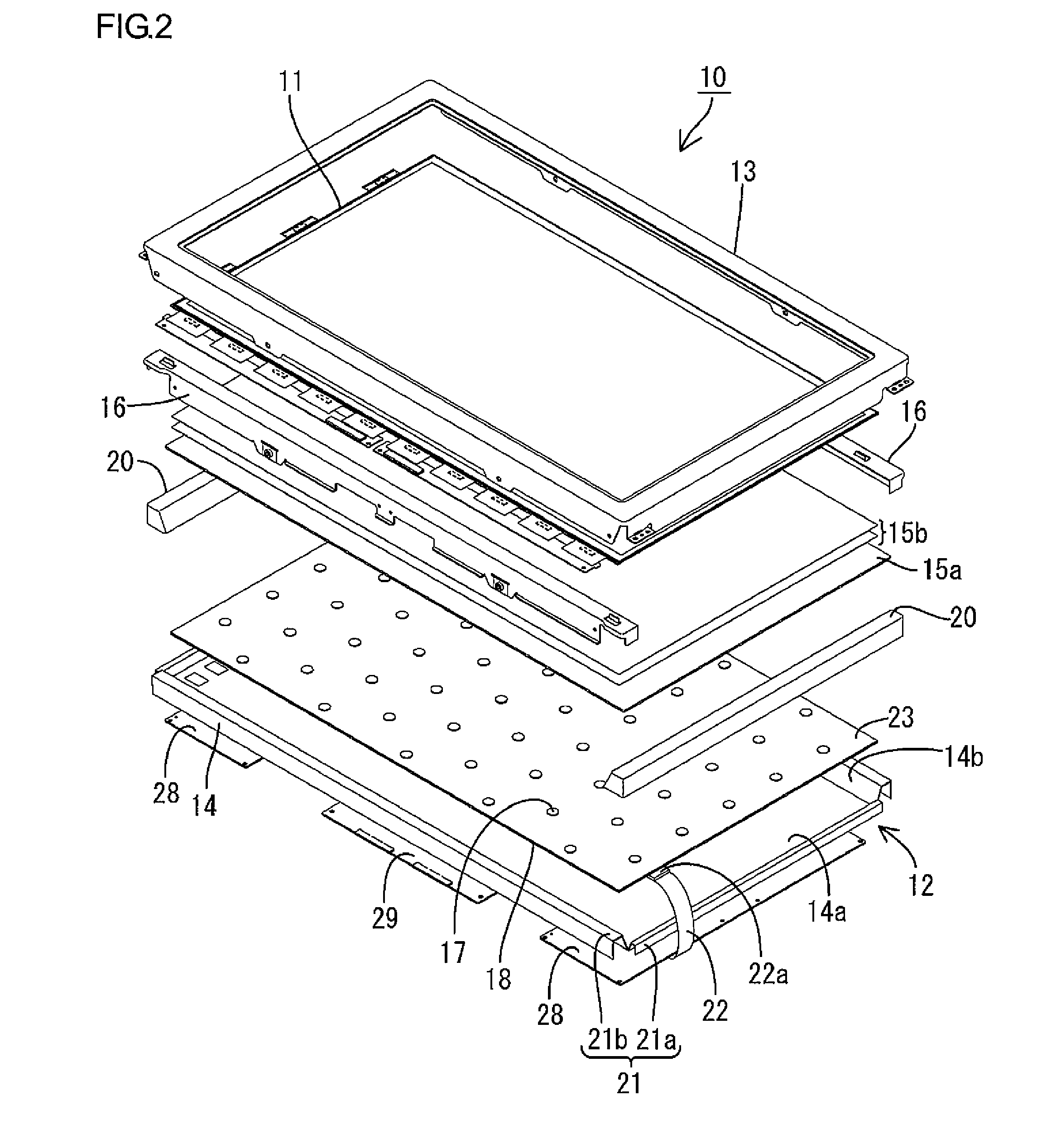
[0045]First, a construction of a television receiver TV including a liquid crystal display device 10 will be explained.

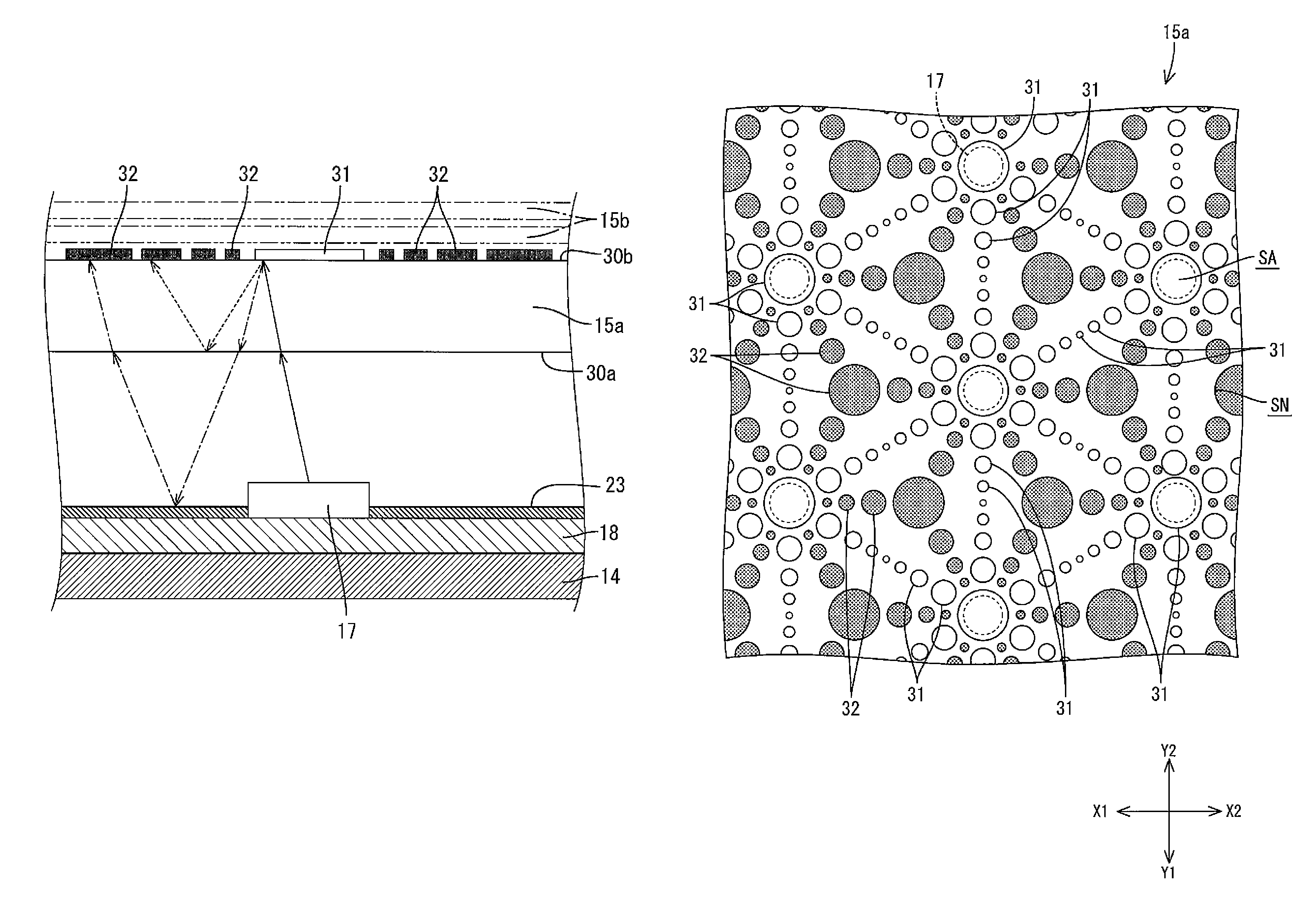
[0046]FIG. 1 is an exploded perspective view illustrating a general construction of the television receiver of this embodiment. FIG. 2 is an exploded perspective view illustrating a general construction of the liquid crystal display device included in the television receiver in FIG. 1. FIG. 3 is a cross-sectional view of the liquid crystal display device in FIG. 2. FIG. 4 is a typical view explaining a cross-sectional construction and an operation of the light guide plate of the liquid crystal display device in FIG. 2. FIG. 5 is a typical view illustrating plan arrangement of the light reflecting portions and the light scattering portions formed on the light guide plate. FIG. 6 is an explanation view illustrating an operation of the light guide plate. FIG. 7 is a gra...

fourth modification

of First Embodiment

[0093]As an additional modification of the arrangement of the light reflecting portions 31 on the second surface 30b of the light guide plate 15a of the first embodiment, the light reflecting portions 31 may be arranged as illustrated in FIG. 11.

[0094]FIG. 11 typically illustrates a pattern example of the light reflecting portions 31 formed on the light guide plate 151a. The light reflecting portion 31 formed on the light guide plate 151a includes a light source overlapped light reflecting portion 131a, a first ring-shaped light reflecting portion 131b, a second ring-shaped light reflecting portion 131c, a third ring-shaped light reflecting portion 131d and a fourth ring-shaped light reflecting portion 131e. The light source overlapped light reflecting portion 31a is provided to overlap the LED light source 17. The first ring-shaped light reflecting portion 131b is formed in adjacent to the light source overlapped light reflecting portion 131a. The second ring-sha...

fifth modification

of First Embodiment

[0096]As an additional modification of the arrangement of the light reflecting portions 31 on the second surface 30b of the light guide plate 15a of the first embodiment, the light reflecting portions 31 may be arranged as illustrated in FIG. 12.

[0097]FIG. 12 typically illustrates a pattern example of the light reflecting portions 31 formed on the light guide plate 152a. The light reflecting portion 31 formed on the light guide plate 152a includes a light source overlapped light reflecting portion 231a and a plurality of dot patterns including dots 231. The dot patterns include a first dot pattern, a second dot pattern and a third dot pattern. The first dot pattern includes a plurality of dots 231 around the light source overlapped light reflecting portion 231a with a predetermined distance therefrom (on a first imaginary circle that is provided a predetermined distance away from the light source overlapped light reflecting portion 231a). The second dot pattern in...


PUM


Abstract

A lighting device 12 includes at least one point light source 17, an optical member 15a provided on a light output side of the lighting device 12 from the point light source 17. The optical member 15a is formed of a member having a substantially uniform light reflectance. A first light reflecting portion 31 is formed on a portion of the optical member 15a that overlaps the point light source 17, and the first light reflecting portion 31 reflects light from the point light source 17. A second light reflecting portion 30a, 23 is provided to reflect the light that is reflected by the first light reflecting portion 31 to be directed to the first light reflecting portion 31.

Description

TECHNICAL FIELD[0001]The present invention relates to a lighting device, a display device and a television receiver.BACKGROUND ART[0002]A liquid crystal panel included in a liquid crystal display device does not emit light, and thus a backlight device is required as a separate lighting device. The backlight device is arranged behind the liquid crystal panel (i.e., on a side opposite from a display surface side). It includes a chassis having an opening on a liquid crystal panel side, a plurality of LEDs (light emitting diodes) accommodated in the chassis as light sources, and a light guide plate and the like that efficiently guides light emitted from the LEDs to the liquid crystal panel.[0003]In such a backlight device, brightness may be remarkably different in a portion in which the LEDs are arranged and a portion in which no LED is arranged. Therefore, the point light emitted from each LED is converted to planer light by an optical member such as the light guide plate to obtain uni...

Claims


Application Information

Patent Timeline
Patent Type & Authority Patents(United States)
IPC IPC(8): G09F13/04G09F13/08F21V7/04
CPCG02B6/0055G02F1/133605G02F1/133606G02F1/133603G02F1/133611
Inventor TAKATA, YOSHIKI
Owner SHARP KK
Why Eureka
Try Eureka