Door lock apparatus

a door lock and door lock technology, applied in the direction of mechanical equipment, mechanical controls, other washing machines, etc., can solve the problems of stopping the washing operation, achieve the effect of ensuring convenience in maintenance and repair, compact structure, and simple structur

Active Publication Date: 2013-06-11
DUAL MECHANICS
View PDF26 Cites 6 Cited by
  • Summary
  • Abstract
  • Description
  • Claims
  • Application Information

AI Technical Summary

Benefits of technology

[0008]The following description relates to a door lock apparatus having a simple, compact structure, which has few failures, ensures convenience in maintenance and repair and reduces the number of assembly steps.
[0010]Therefore, since the position fixing rod is integrated into the rocker, the rocker can have a simple, compact structure. Accordingly, the door lock apparatus may have few failures, ensure convenience in maintenance and repair and reduce the number of assembly steps. Further, since the coupled or separated state of the rocker and hook can be stably maintained due to the inter-action between the position fixing rod and the position fixing hole, incorrect operation can be prevented through a relatively simple structure, which leads to high reliability and safety.
[0011]When a user tries to forcibly open the door while the rocker is locked so as to detach only the hook from the rocker though maintaining the rocker in its current position, the user can manually move the rocker to a position at which the rocker can be again coupled with the hook. Accordingly, the door lock apparatus has fewer failures, resulting in a reduction of economic loss due to replacement.

Problems solved by technology

If the door opens during washing, the laundry and detergent water solutions may be discharged out of the machine, so that the washing operation is stopped and in the worse case an accident involving personal injury may occur by the rotating drum.

Method used


Image

  • Door lock apparatus
  • Door lock apparatus
  • Door lock apparatus

Examples


Embodiment Construction

[0020]The following description is provided to assist the reader in gaining a comprehensive understanding of the methods, apparatuses, and / or systems described herein. Accordingly, various changes, modifications, and equivalents of the methods, apparatuses, and / or systems described herein will be suggested to those of ordinary skill in the art. Also, descriptions of well-known functions and constructions may be omitted for increased clarity and conciseness.

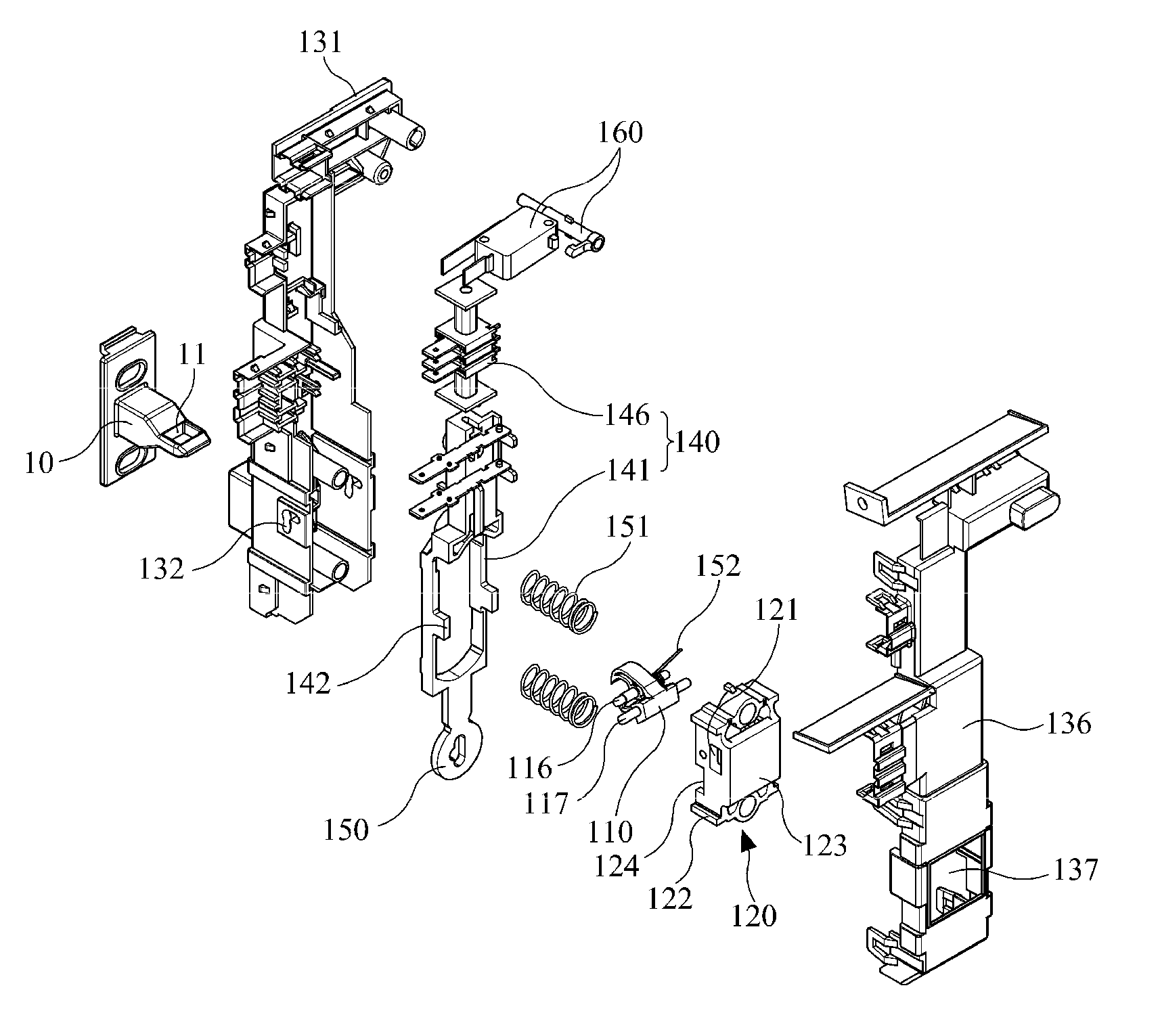
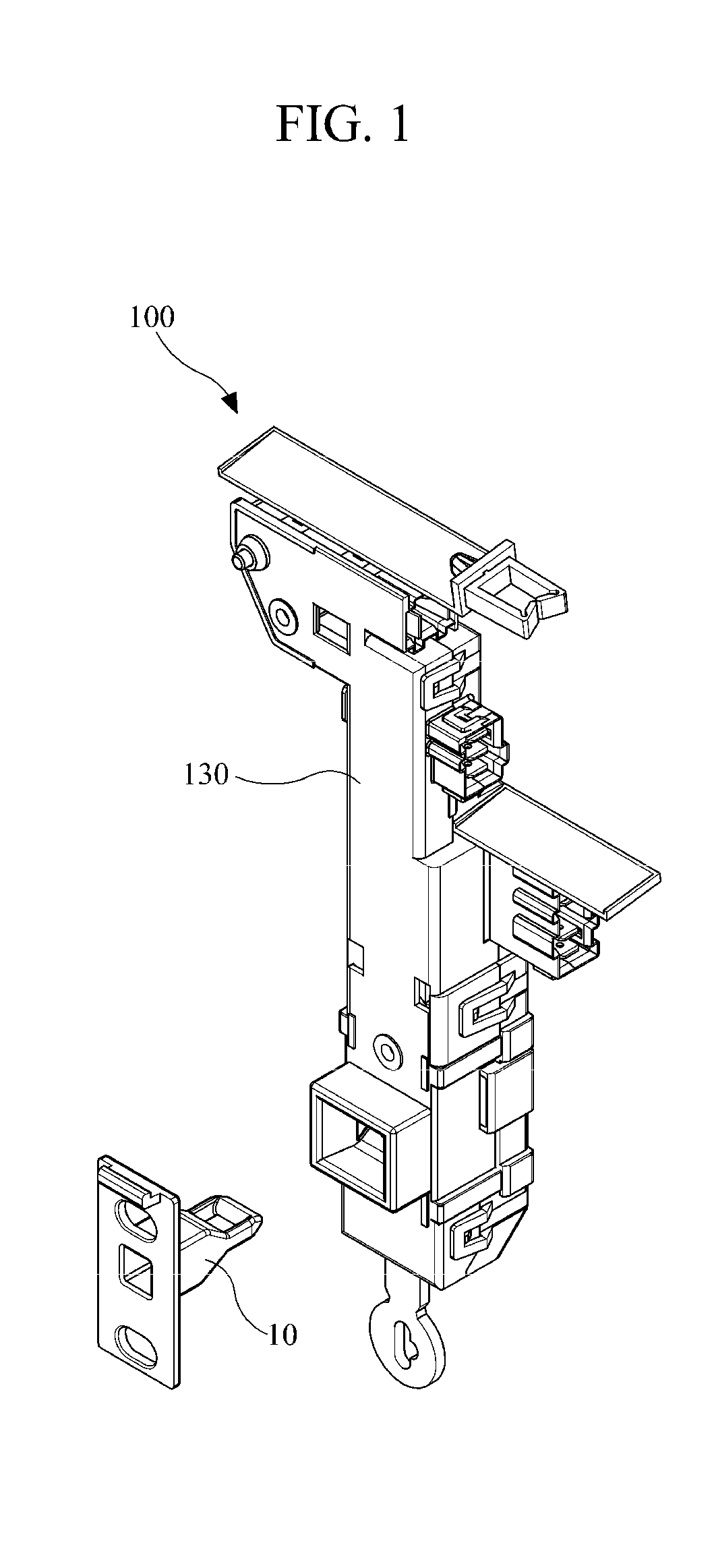
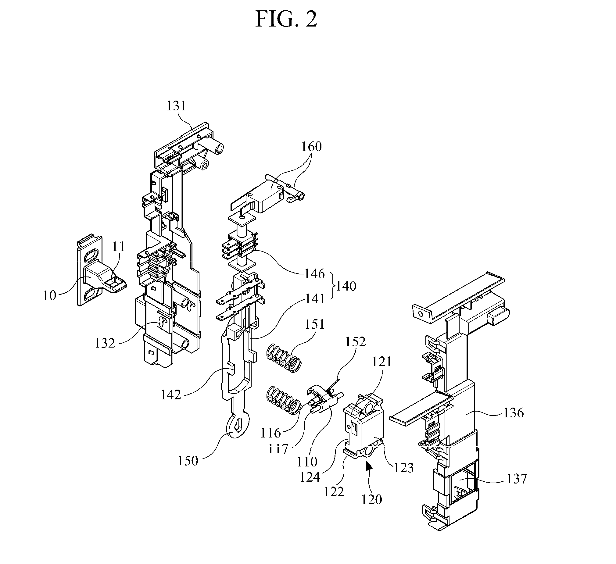
[0021]FIG. 1 is a perspective view illustrating an example of a door lock apparatus 100, and FIG. 2 is an exploded, perspective view of the door lock apparatus 100 illustrated in FIG. 1. FIG. 3 is a side sectional view of the door lock apparatus 100 illustrated in FIG. 1 and FIG. 4 is an enlarged view of a part A of FIG. 3.

[0022]Referring to FIGS. 1 through 4, the door lock apparatus 100 is adopted in various electronic products including a drum washing machine to lock or release a door, and the door lock apparatus 100 includes a ...


PUM


Abstract

Provided is a door lock apparatus which is adopted in an electronic product to lock or release a door of the door lock apparatus. The door lock apparatus includes a rocker, a rocker supporting member, a door lock main body and a locking unit. The rocker rotates when the hook of the door enters or withdraws from the door lock apparatus, to be coupled with or separated away from the hook. A rocker hinge rod and a position fixing rode positioned in parallel to the rocker hinge rod are integrated into the rocker. The rocker supporting member is hinge-coupled with the rocker hinge rod to rotatably support the rocker, reciprocatingly moves in a direction in which the hook enters or withdraws when the rocker is rotated, and receives an elastic force from a first elastic member in the direction in which the hook enters. The door lock main body supports the reciprocating movement of the rocker supporting member, and includes position fixing holes to guide movement of the rocker while being coupled with the position fixing rod when the rocker rotates and to fix the rocker while the rocker is coupled with or separated from the hook. The locking unit locks the rocker while the rocker is coupled with the hook. Accordingly, the door lock apparatus has a simple, compact structure, which has fewer failures, ensures convenience in maintenance and repair and reduces the number of assembly steps.

Description

CROSS-REFERENCE TO RELATED APPLICATION[0001]This application claims the benefit under 35 U.S.C. §119(a) of a Korean Patent Application No. 10-2010-0017205, filed on Feb. 25, 2010, the entire disclosure of which is incorporated herein by reference for all purposes.BACKGROUND[0002]1. Field[0003]The following description relates to a door lock apparatus, and more particularly, to a door lock apparatus used to lock or release a door of an electronic product.[0004]2. Description of the Related Art[0005]A drum washing machine which is a kind of electronic product includes a large aperture in a front side through which to put laundry and a door mounted therein to open or close the aperture. Upon operation, a drum of the drum washing machine washes the laundry with a head force and a friction force while rotating centered on a horizontal axis. Such a drum washing machine includes a door lock apparatus to automatically lock the door in order to prevent the door from opening during washing. I...

Claims


Application Information

Patent Timeline
Patent Type & Authority Patents(United States)
IPC IPC(8): E05C3/06E05C5/00E05C9/12E05C1/06
CPCD06F37/42D06F39/14E05B47/0603E05C5/02E05B47/0002E05B2047/0068E05B2047/0086E05C3/24D06F34/20D06F2103/40Y10T70/5155Y10T70/625Y10T70/7062Y10T292/0862Y10T292/0886Y10T292/1016Y10T292/1082
Inventor SUH, SANG-WONCHOI, CHEONG-WON
Owner DUAL MECHANICS
Why Eureka
Try Eureka