Check patentability & draft patents in minutes with Patsnap Eureka AI!

Solvent delivery pump and liquid chromatograph

a solvent delivery pump and liquid chromatograph technology, applied in the direction of positive displacement liquid engines, liquid fuel engines, instruments, etc., can solve the problems of difficult to reduce the frictional force between the plunger and the plunger seal without such a mechanism, shorten the life of the plunger seal, etc., to reduce the installation space of the solvent delivery pump, simplify the piping structure, and reduce the friction between the plunger seal and the plunger

Inactive Publication Date: 2013-07-16
SHIMADZU CORP
View PDF4 Cites 1 Cited by
  • Summary
  • Abstract
  • Description
  • Claims
  • Application Information

AI Technical Summary

Benefits of technology

This approach reduces friction between the plunger and plunger seal without additional mechanisms, reducing the device's size and simplifying installation, while preventing salt deposition and extending the seal's lifespan.

Problems solved by technology

This shortens the life of the plunger seal.
Conventionally, however, it is difficult to reduce the frictional force between the plunger and the plunger seal without such a mechanism.

Method used


Image

  • Solvent delivery pump and liquid chromatograph
  • Solvent delivery pump and liquid chromatograph
  • Solvent delivery pump and liquid chromatograph

Examples


Embodiment Construction

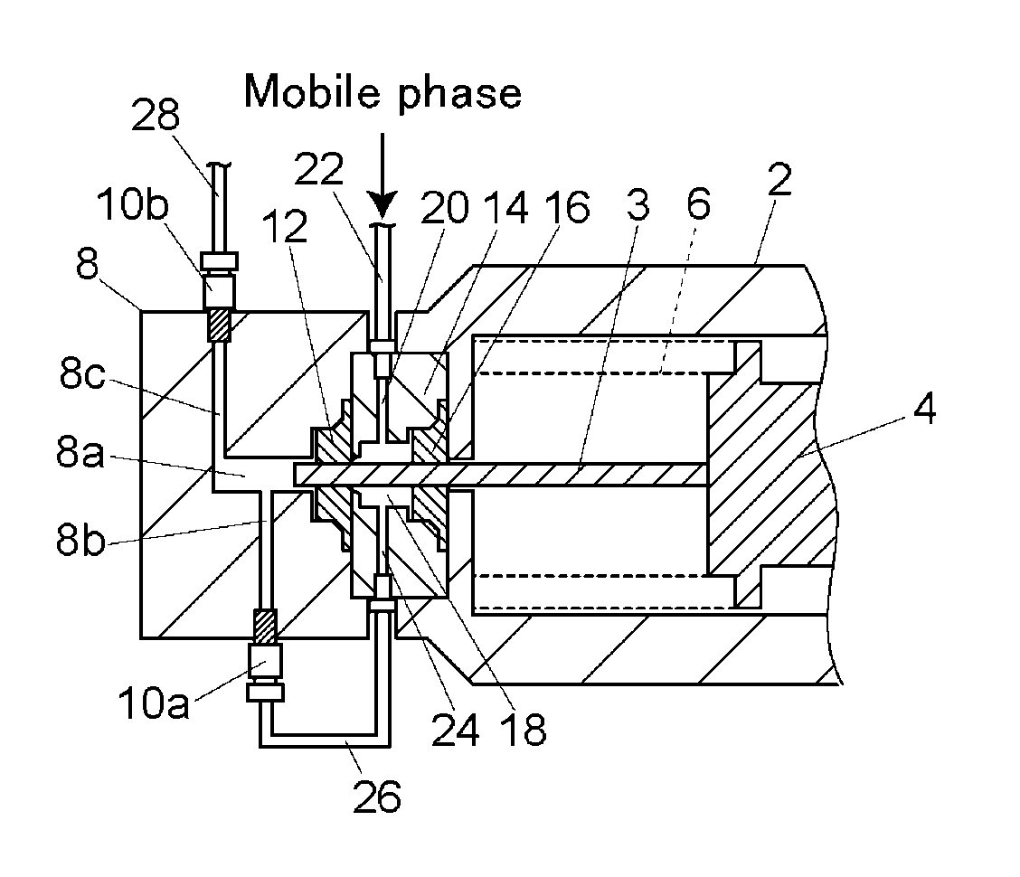
[0019]An embodiment of a solvent delivery pump will be described with reference to FIG. 1. A pump head 8 is provided to the tip end portion of a pump body 2. The pump head 8 includes, in itself, a pump chamber 8a, a sucking flow path 8b, and a discharge flow path 8c. The sucking flow path 8b is a flow path for taking a mobile phase into the pump chamber 8a and one end of a pipe 26 as a mobile phase flow path is connected to an end portion of the sucking flow path 8b via a check valve 10a. The other end of the pipe 26 is connected to a flow path 24 of a seal holder 14 which will be described later. The discharge flow path 8c is a flow path for discharging the mobile phase sucked into the pump chamber 8a and a pipe 28 is connected to an end portion of the discharge flow path 8c via a check valve 10b. The pipe 28 for example forms an analytical flow path connected from an analytical column of a liquid chromatograph to a detector.

[0020]A cross head 4 is housed in the pump body 2 and a p...


PUM

PropertyMeasurementUnit
pressureaaaaaaaaaa
solventaaaaaaaaaa
liquidaaaaaaaaaa

Abstract

A cleaning chamber is provided in a seal holder and two cleaning chamber flow paths communicating with the cleaning chamber from outside are provided. A pipe connected to a vessel storing a mobile phase is connected to one of the cleaning chamber flow paths. A pipe as a flow path connected to a mobile phase sucking flow path into a pump chamber is connected to the other cleaning chamber flow path. When the mobile phase is taken in, the mobile phase is sucked into the pump chamber via the cleaning chamber.

Description

BACKGROUND OF THE INVENTION[0001]1. Field of the Invention[0002]The present invention relates to a solvent delivery pump for sucking and discharging a mobile phase by reciprocating a plunger on a straight line and a liquid chromatograph using the solvent delivery pump.[0003]2. Description of the Related Art[0004]In a solvent delivery pump used for sending a mobile phase in a liquid chromatograph, if the solution sending pressure becomes high over 50 MPa, frictional force between a plunger seal sealing a pump chamber and a plunger becomes large. This shortens the life of the plunger seal. Therefore, in order to reduce the frictional force between the plunger seal and the plunger, a mechanism for supplying a cleaning solution to portions of the plunger seal and the plunger sliding on each other to wet an outer peripheral face of the plunger is proposed (see Japanese Patent Application Laid-Open No. 10-238475).[0005]FIG. 3 shows an example of a solvent delivery pump having such a funct...

Claims


Application Information

Patent Timeline
Patent Type & Authority Patents(United States)
IPC IPC(8): G01N1/00F04B41/06
CPCF04B53/162G01N30/32G01N2030/326
Inventor ASO, YOSHIAKI
Owner SHIMADZU CORP
Features
  • R&D
  • Intellectual Property
  • Life Sciences
  • Materials
  • Tech Scout
  • Unparalleled Data Quality
  • Higher Quality Content
  • 60% Fewer Hallucinations
Learn More