Door lock transmission structure

Inactive Publication Date: 2013-09-24
TSAI MIAO HSUEH
View PDF5 Cites 12 Cited by
  • Summary
  • Abstract
  • Description
  • Claims
  • Application Information

AI Technical Summary

Benefits of technology

[0006]Therefore, it is a primary objective of the present invention to overcome the aforementioned shortcomings of the prior art by providing a door lock transmission structure, wherein a second insert of a primary lock assembly can be opened by turning a door handle installed on an internal side of a door directly, and the second insert is driven to open a first insert and a secondary lock assembly, such that the door can be opened conveniently at regular time, and quickly at fire or any other emergency situation to provide a safe escape.
[0007]Another objective of the present invention is to provide a power-saving mechanism installed between components of the primary lock assembly to provide a power-saving way of locking and unlocking the door.

Problems solved by technology

If there is a fire, and users have to escape for their survival, such conventional door lock may delay the escape, and thus the conventional door lock requires improvements on safety.

Method used


Image

  • Door lock transmission structure
  • Door lock transmission structure
  • Door lock transmission structure

Examples


Embodiment Construction

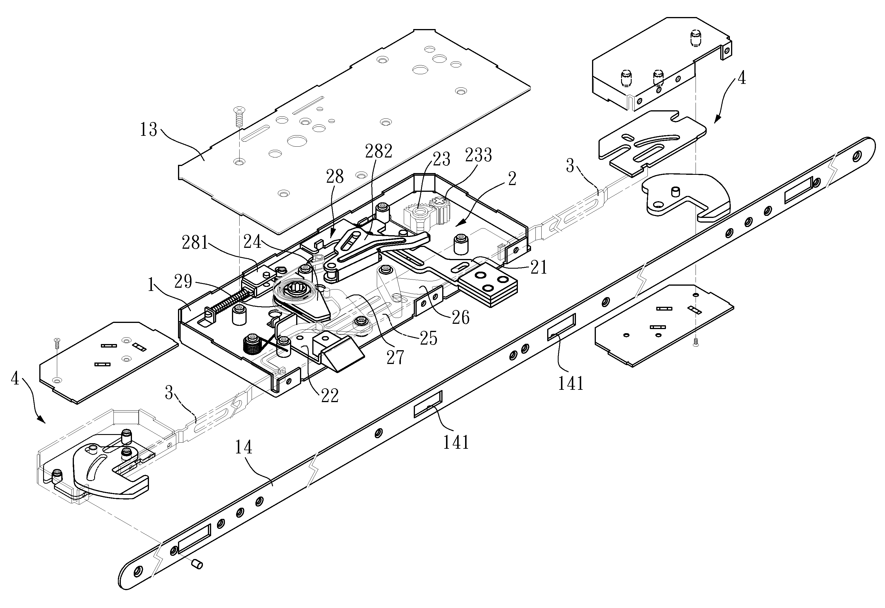
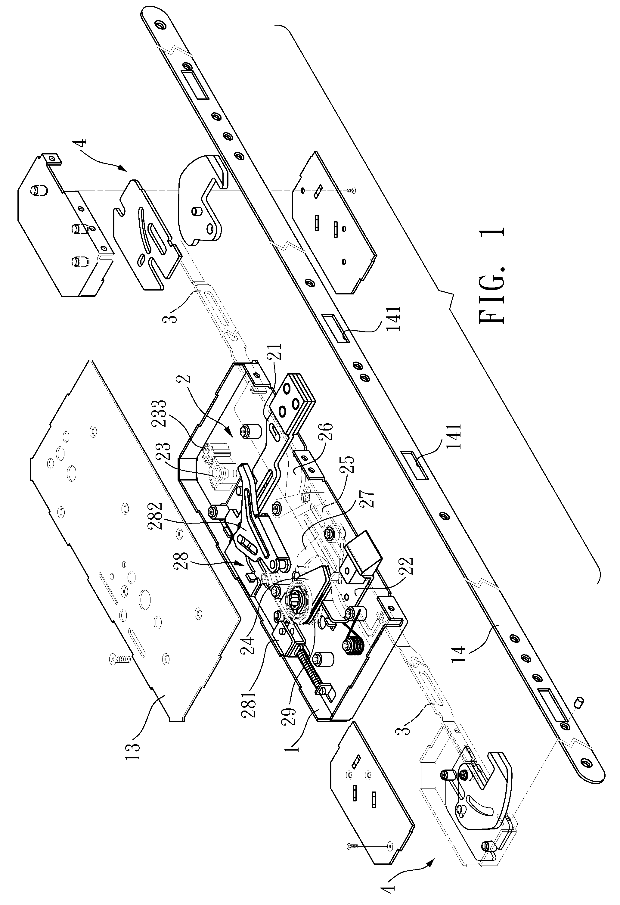
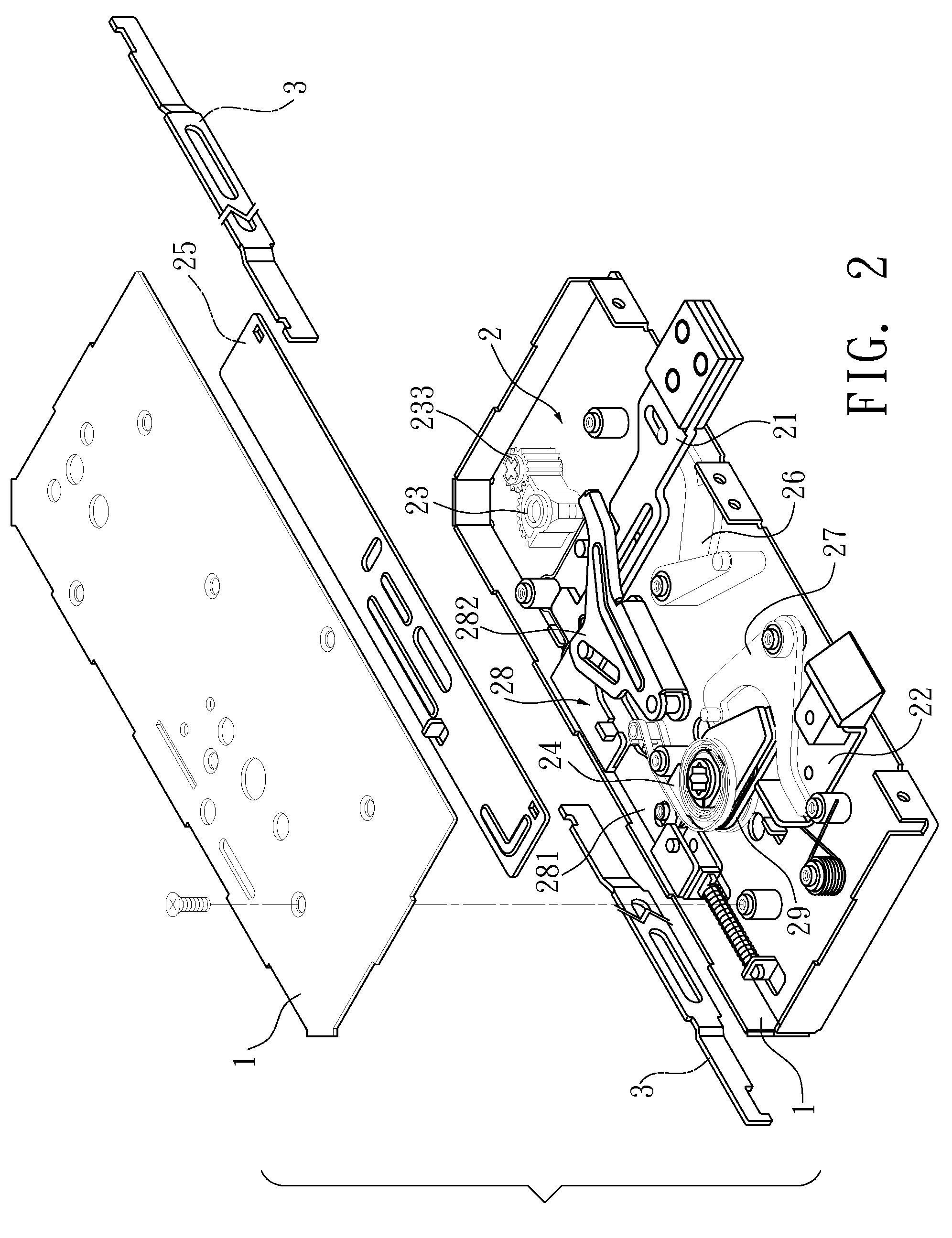
[0026]With reference to FIGS. 1 to 7 for a preferred embodiment of the present invention, this embodiment is provided for the purpose of illustrating the present invention only, but not intended for limiting the scope of the invention.

[0027]This preferred embodiment provides a door lock transmission structure, comprising: a case 1, including a plurality of protruding pillars 11 and through holes 12 for installing a primary lock assembly 2 (wherein the case 1 of this preferred embodiment as shown in the figures further comprises components such as a cover 13 secured onto the case 1 by screws and a side panel 14 installed on a side of a door), and the primary lock assembly 2 including a link rod 3 installed at upper and lower position of the door for driving a secondary lock assembly 4, and the primary lock assembly 2 comprises the following elements:

[0028]A first insert 21 and a second insert 22 are movably installed in the case 1, and each insert 21, 22 has a latch portion 211, 221 ...


PUM


Abstract

A door lock transmission structure includes two inserts and a link component installed in a case, and the two inserts are driven by a key and a door handle respectively. The insert driven by the door handle includes two driving elements for driving one of the inserts to operate, such that the two inserts are driven for a synchronous operation when one of the driving elements is operated, so as to constitute the door lock transmission structure.

Description

BACKGROUND OF THE INVENTION[0001]1. Field of the Invention[0002]The present invention relates to a door lock, and more particularly to a door lock structure driven by a primary lock assembly and a secondary lock assembly for its operation.[0003]2. Description of the Related Art[0004]With reference to FIGS. 8 and 9 for a conventional door lock, the door lock comprises a case 90, and a first insert 91 and a second insert 92, both installed in the case 90, wherein the first insert 91 drives a link rod module 93 by a key to slide inside the case 90 and link both upper and lower locks of a door, and the second insert 92 is driven by a door handle to move a driving element 94 and link the driving element 94 to slide in the case 90, and the first insert 91 and the second insert 92 as shown in the figures are driven by the key and the door handle respectively.[0005]The main problem of the conventional door lock resides on that when both first insert 91 and second insert 92 are locked (and t...

Claims


Application Information

Patent Timeline
Patent Type & Authority Patents(United States)
IPC IPC(8): E05C5/00
CPCE05B59/00E05C9/026E05B65/1086Y10T292/0825Y10T292/0887Y10T292/57
Inventor TSAI, MIAO-HSUEH
Owner TSAI MIAO HSUEH
Why Eureka
Try Eureka