Stuffing device

a technology of stacking device and stout, which is applied in the direction of baling, agriculture tools and machines, agriculture, etc., can solve the problems of relative complex construction of the mechanical linkage system and low flexibility of the arm movement trajectory

Active Publication Date: 2013-10-22
LELY PATENT
View PDF12 Cites 17 Cited by
  • Summary
  • Abstract
  • Description
  • Claims
  • Application Information

AI Technical Summary

Benefits of technology

[0014]It is an aim of the invention to provide an alternative agricultural piston bale press of relative simple design, wherein the stuffing device preferably provides more flexibility in the trajectories of the arm of the stuffing device.
[0018]By making the second driving device mechanically independent of the main driving mechanism, the fulcrum pivotably supporting the arm may be moved independent of the oscillating movement of the piston press. As a result, the flexibility of the movements that can be made by the arm is substantially increased.
[0021]By providing an adjustable second driving device the distance and / or speed of displacement of the fulcrum may be adjusted to the circumstances of the stuffing process or other variables. For instance, it may be possible to increase the speed of the arm in parts of the trajectory in which the arm does not have to exert a pressure on crop material. Also, it may be possible to decrease the distance of displacement of the fulcrum from the first position to an intermediate position between the first and second position. As a result, the trajectory of the tines will be longer than the smaller stuffing cycle with no movement of the fulcrum, but smaller than the load cycle. Such intermediate cycle may for instance be useful to adapt a stuffing trajectory to the kind of crop material and the moisture content of the crop material. As it is possible to adjust distance and / or speed of displacement of the arm any suitable trajectory can be designed. In an embodiment, it may also be possible to adjust the maximum force exerted by the arm.
[0024]In contrast, when the hydraulic actuators are actuated serially the force exerted on the fulcrum will be equal to the force of one actuator, but the speed with which the fulcrum can be moved will be increased. Such increased speed is in particular useful when no or little force has to be exerted by the arm, for instance in the part of the load cycle where the tines are mainly positioned outside the feed passage and the arm is moved back to beginning of the load cycle.
[0025]In an embodiment, the second driving device comprises a hydraulic rotary actuator. Such rotary actuator is very practical for movement of the fulcrum. For instance, when a crank or other arm like element is arranged on the shaft of the rotary actuator and the fulcrum is connected to the crank or arm, for instance by a rod or such, rotation of the rotary actuator over an angle, will rotate the crank or arm therewith moving the fulcrum between different positions. Preferably, the rotary actuator comprises a sensor to directly or indirectly measure a rotary position of the hydraulic rotary actuator. The output of such sensor will provide direct information on the position of the fulcrum.
[0027]In an embodiment, the retaining element is mechanically linked with the second driving device, such that when the second driving device displaces the fulcrum for a load trajectory, the retaining element is moved to the non-retaining position. By actively moving the retaining element out of the feed passage at the beginning of the load trajectory, the second driving device does not have to provide an extra force to push the retaining element out of the feed passage. As a result, more force will be available for pushing the compressed crop material out of the feed passage.

Problems solved by technology

A drawback of the bale press of EP '674 is that the mechanical linkage system has a relative complex construction.
Furthermore, the mechanical linkage system of EP '674 provides low flexibility with respect to the trajectory of movement of the arm.

Method used


Image

  • Stuffing device
  • Stuffing device
  • Stuffing device

Examples


Embodiment Construction

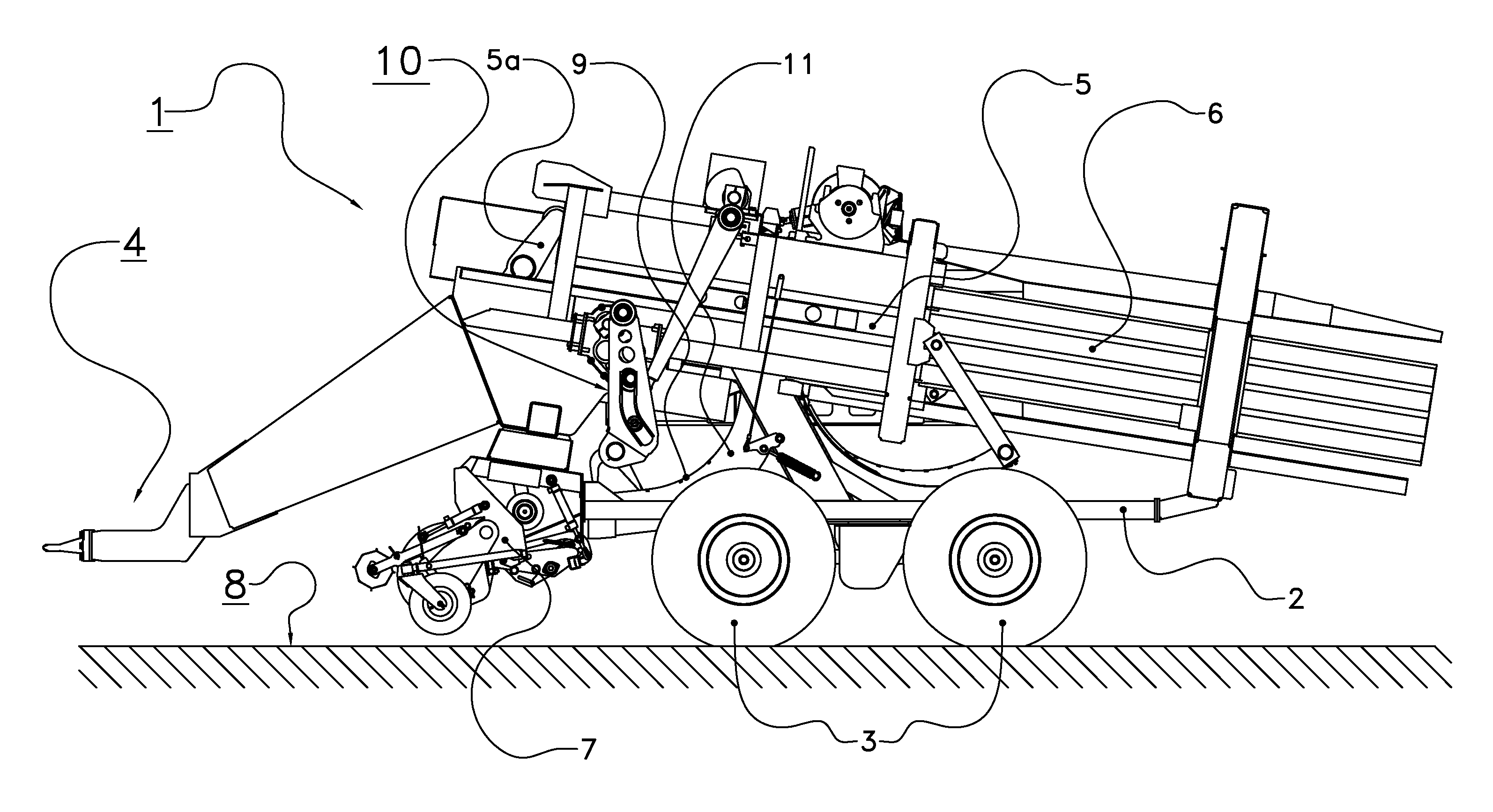
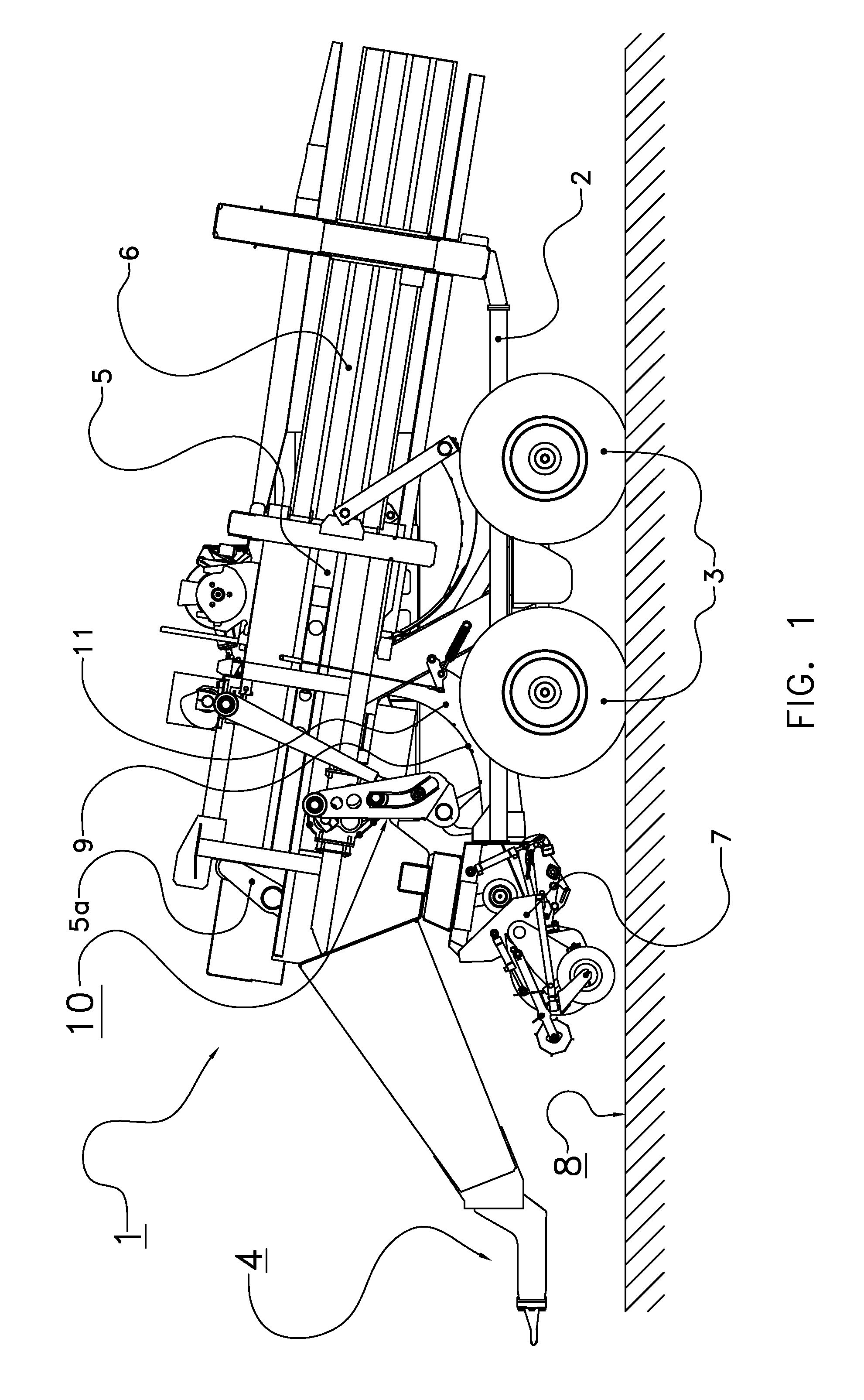
[0033]The following is a description of certain embodiments of the invention, given by way of example only and with reference to the drawings. FIG. 1 shows a side view of a piston bale press, generally denoted with the reference numeral 1. Piston bale presses of this type are generally known and for instance disclosed in EP 1 769 674, EP 0870 425, and U.S. Pat. No. 4,106,268, which are all hereby incorporated by reference in their entireties.

[0034]The piston bale press comprises a frame 2 supported by wheels 3. The piston bale press 1 is configured to be connected at its front end 4 to a pulling vehicle, for instance a tractor. The piston bale press 1 further comprises a piston press 5 configured to press crop material in rectangular bales in a bale chamber 6. A main drive mechanism 5a is provided to move the piston press 5 in an oscillating movement in the bale chamber 6 to compress crop material in the bale chamber 6. The piston bale press 1 further comprises an intake device 7 to...


PUM


Abstract

The invention relates to an agricultural piston bale press. This press includes a pressing piston arranged in a bale chamber, an intake device to take in crop material, and a stuffing device, wherein the stuffing device includes a feed passage and a stuffing mechanism, the stuffing mechanism includes an arm supporting tines, wherein said arm is movable by a first driving device to at least move the tines in and out of the feed passage and wherein said arm is pivotably supported by a fulcrum, the fulcrum being displaceable to selectively move the arm along the stuffing trajectory or load trajectory. The stuffing device includes a second driving device to displace the fulcrum, and in that the second driving device is mechanically independent of the main driving mechanism.

Description

CROSS REFERENCE TO RELATED APPLICATIONS[0001]This application is a continuation of PCT application number PCT / NL2010 / 000150 filed on 21 Oct. 2010, which claims priority from Netherlands application number 1037434 filed on 2 Nov. 2009, as well as from Netherlands application number 1037453 filed on 6 Nov. 2009. All applications are hereby incorporated by reference in their entireties.BACKGROUND OF THE INVENTION[0002]1. Field of the Invention[0003]The present invention relates to a piston bale press for forming rectangular bales of crop material.[0004]2. Description of the Related Art[0005]Such piston bale presses are for instance disclosed in EP 1 769 674, EP 0870 425, and U.S. Pat. No. 4,106,268, which are hereby incorporated by reference in their entireties.[0006]EP 1 769 674 discloses an agricultural piston bale press, comprising:[0007]a pressing piston arranged in a bale chamber to form bales or crop material[0008]a main driving mechanism to drive the pressing piston in an oscill...

Claims


Application Information

Patent Timeline
Patent Type & Authority Patents(United States)
IPC IPC(8): A01F15/10B30B15/30B30B9/30
CPCA01F15/101A01F2015/102B30B9/3007
Inventor BERGMANN, THOMAS
Owner LELY PATENT
Why Eureka
Try Eureka