Bone fusion device

a bone fusion and bone technology, applied in the field of bone fusion devices, can solve the problems of degenerative disc disease, pain that radiates into other parts of the body, and may cause instability of the vertebrae,

Active Publication Date: 2013-12-03
NEUROPRO TECH
View PDF144 Cites 119 Cited by
  • Summary
  • Abstract
  • Description
  • Claims
  • Application Information

AI Technical Summary

Benefits of technology

[0013]The present invention is a bone fusion device for insertion between bones that are to be fused together, such as, for example, the vertebrae of a spinal column. The bone fusion device comprises one or more extendable tabs. The bone fusion device is in its most compact state when the tabs are aligned with the body of the device such that the tabs lie within the exterior of the device. In this compact form, the bone fusion device is preferably inserted between the vertebrae by using an arthroscopic procedure. The bone fusion device of some embodiments is filled with bone graft material. In these embodiments, the bone graft material is typically relocated from the interior to the exterior of the bone fusion device by using a lead screw. After the device has been positioned between the vertebrae, and the lead screw is inserted to optionally deliver the bone graft material, selected tabs are extended. Preferably, two tabs are extended upon rotating a rotating means wherein extending blocks travel up the screw pushing out the angled tabs as the extending blocks approach the ends of the bone fusion device. The position of each tab relative to the bone fusion device is adjustable depending upon the configuration of the associated rotating means. In this way, the tabs are advantageously positioned in the confined space between the vertebrae to help brace the device until the bone has fused. Further, the tabs of the bone fusion device provide a larger surface area to which the bones attach and fuse during a healing period.
[0014]In some embodiments, the body of the bone fusion device is a round cylinder with end faces. The bone fusion device has conduits or holes that allow the bone graft material within the device to flow to the exterior of the device where the material contacts and grafts to the vertebrae. The extendable tabs are arranged in various configurations on the exterior of the bone fusion device, including the end faces. Preferably, the bone fusion device is rectangular and the tabs are attached to the body of the device on more than one side to optimally brace the device from multiple directions between the adjacent vertebrae. Alternatively, the bone fusion device has a rectangular shape with end faces and extendable tabs attached to multiple exterior surfaces. In some embodiments, the bone fusion device of some embodiments includes protrusions, threading, and / or sharp features on the exterior surface and / or the extendable tabs. These features are configured to engage the adjacent vertebrae to provide a tighter interface between the device and the vertebrae. In some embodiments, the tabs comprise stops to prevent the tabs from extending too far out of the body. In some embodiments, the device comprises a radio frequency identifier chip for providing information about the device and / or other information. In some embodiments, the device comprises one or more retention springs for biasing the tabs in the retracted position. In some embodiments, the tabs comprise a plurality of nested levels that enable the extending of the tabs to comprise the telescoping of the levels in order to increase stability and the amount of extension. In some embodiments, the tabs comprise one or more tongues that increase the top surface area of the tabs such that there is more surface area to contact and fuse to the bones.

Problems solved by technology

Injury, disease, or excessive pressure on the discs can cause degenerative disc disease or other disorders where the disc becomes thinner and allows the vertebrae to move closer together or become misaligned.
As a result, nerves may become pinched, causing pain that radiates into other parts of the body, or instability of the vertebrae may ensue.
Such an invasive surgical procedure requires a long recovery period.

Method used


Image

  • Bone fusion device
  • Bone fusion device
  • Bone fusion device

Examples


Embodiment Construction

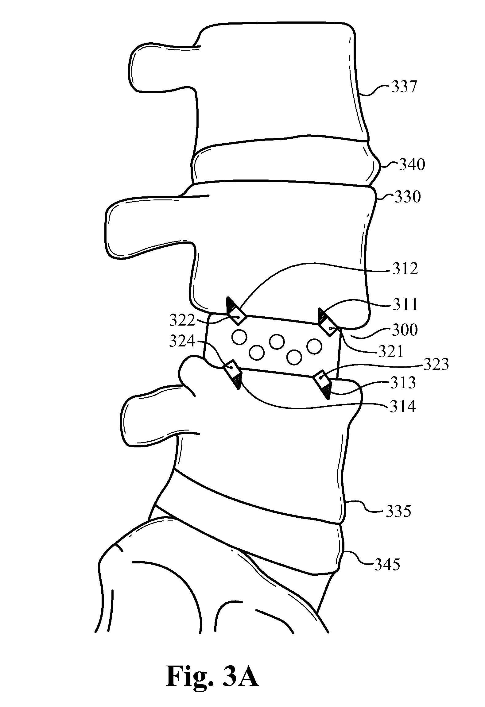
[0068]In the following description, numerous details and alternatives are set forth for purpose of explanation. However, one of ordinary skill in the art will realize that the invention can be practiced without the use of these specific details. For instance, the figures and description below often refer to the vertebral bones of a spinal column. However, one of ordinary skill in the art will recognize that some embodiments of the invention are practiced for the fusion of other bones, including broken bones and / or joints. In other instances, well-known structures and devices are shown in block diagram form in order not to obscure the description of the invention with unnecessary detail.

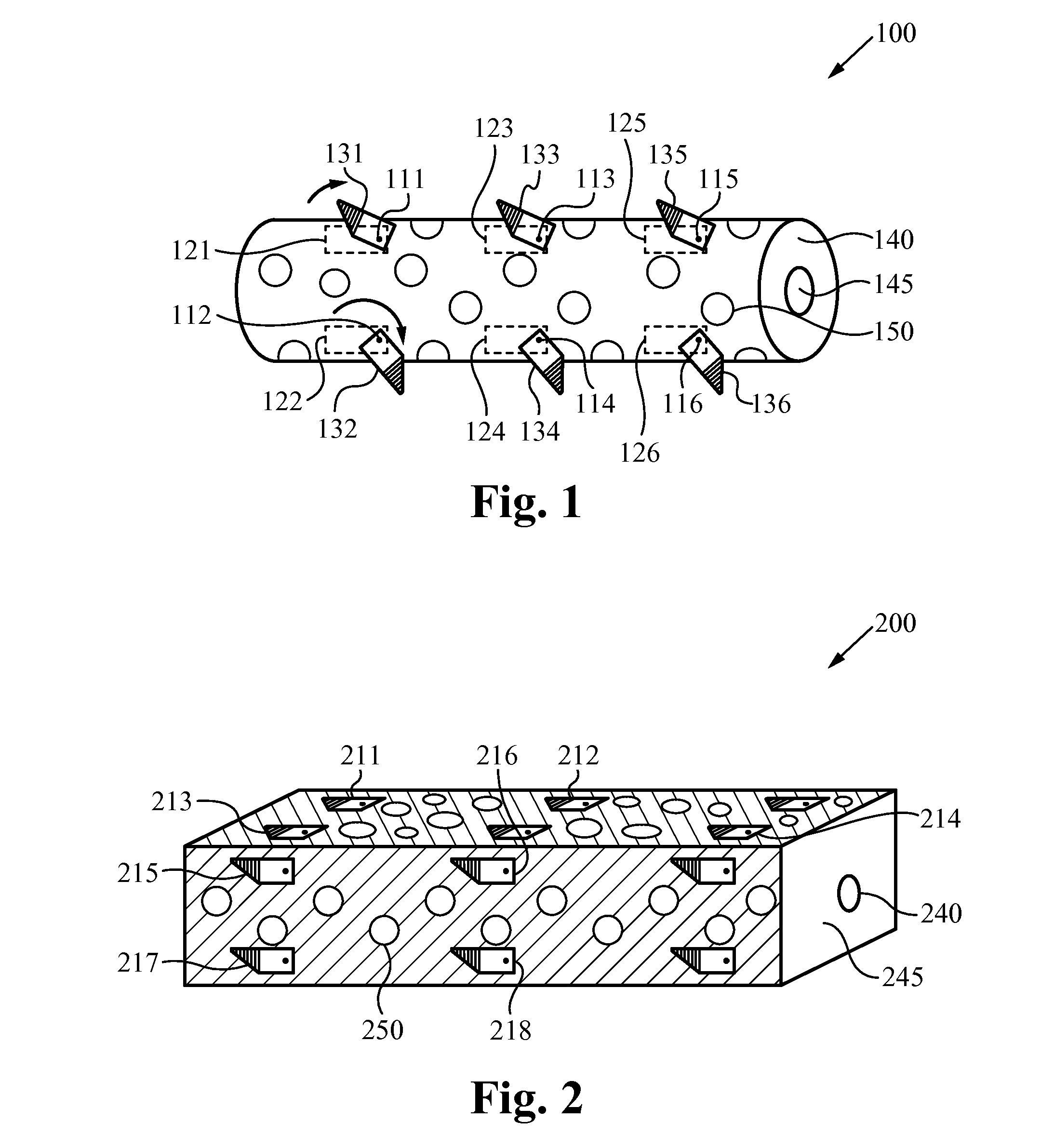
[0069]FIG. 1 illustrates a bone fusion device 100 in accordance with some embodiments of the invention. As shown in this figure, the bone fusion device 100 has a round cylindrical shape and has two end faces, including the end face 140. In some embodiments, the bone fusion device 100 is constructed fr...


PUM

PropertyMeasurementUnit
angleaaaaaaaaaa
lengthaaaaaaaaaa
lengthaaaaaaaaaa

Abstract

A bone fusion device provides stability to bones during a bone fusion period. The bones include, for example, the vertebrae of a spinal column. The bone fusion device comprises one or more extendable tabs attached to the bone fusion device by associated rotating means. The bone fusion device is preferably inserted by using an arthroscopic surgical procedure. During arthroscopic insertion of the device, the tabs are pre-configured for compactness. In this compact configuration, the tabs are preferably deposed along and / or within an exterior surface of the bone fusion device. After the bone fusion device has been positioned between the bones, one or more tab(s) are extended. In the preferred embodiment, the position of each tab is related to a positioning element and extending blocks. Typically, the tabs advantageously position and brace the bone fusion device in the confined space between the bones until the bones have fused.

Description

RELATED APPLICATIONS[0001]This application is a continuation-in-part of U.S. patent application Ser. No. 11 / 484,379, filed on Jul. 10, 2006 and entitled “BONE FUSION DEVICE,” which is a continuation-in-part of U.S. Pat. No. 7,727,280, issued on Jun. 1, 2010 and entitled “BONE FUSION DEVICE,” which is a continuation-in-part of abandoned U.S. patent application Ser. No. 11 / 264,958, filed on Nov. 1, 2005 and entitled “BONE FUSION DEVICE,” and which claims priority under 35 U.S.C. §119(e) of the expired U.S. Provisional Patent Application Ser. No. 60 / 624,836, filed Nov. 3, 2004, and entitled “BONE FUSION DEVICE,” all of which are hereby incorporated by reference. Additionally, this application claims priority under 35 U.S.C. §119(e) of U.S. Provisional Patent Application Ser. No. 61 / 624,155, filed Apr. 13, 2012, and entitled “BONE FUSION DEVICE,” which is hereby incorporated by reference.FIELD OF THE INVENTION[0002]This invention relates generally to bone fusion devices. More specifical...

Claims


Application Information

Patent Timeline
Patent Type & Authority Patents(United States)
IPC IPC(8): A61F2/44
CPCA61F2/4455A61F2/446A61F2/447A61F2/4611A61B17/70A61F2/28A61F2/44A61F2002/2817A61F2002/2835A61F2002/30411A61F2002/30492A61F2002/30507A61F2002/30525A61F2002/30538A61F2002/30556A61F2002/30579A61F2002/30784A61F2002/30841A61F2002/3085A61F2002/30904A61F2002/3092A61F2220/0025A61F2250/0006A61F2250/0009A61F2310/00023A61F2310/00976A61F2002/30266A61F2002/30505A61F2002/30528A61F2002/30565A61F2002/30777A61B2017/0256A61F2002/4627A61F2002/4629A61B2019/461A61B2019/4857A61B2090/061A61B2090/0811A61F2002/30224A61F2002/30263A61F2220/0016
Inventor MCLUEN, GARY R.REMINGTON, BENJAMIN J.BAKER, DANIEL R.LOGAN, JOSEPH N.STALCUP, GREGORY C.
Owner NEUROPRO TECH
Why Eureka
Try Eureka