Dial plate structure and watch

a technology of dial plate and structure, applied in the field of dial plate structure and watch, can solve the problems of poor appearance, difficult surface treatment of the outer periphery of the sub needle or the discoid needle, etc., and achieve the effect of improving visual quality and simple structur

Active Publication Date: 2014-05-20
CASIO COMPUTER CO LTD
View PDF21 Cites 5 Cited by
  • Summary
  • Abstract
  • Description
  • Claims
  • Application Information

AI Technical Summary

Benefits of technology

[0009]The present invention is made, in view of the above mentioned problems, to provide a dial structure and a watch which can improve a visual quality around the rotary indicator with a simple structure.

Problems solved by technology

Therefore, it cannot be helped that the outer periphery of the sub needle or the discoid needle is roughly finished.
Thus, there is a problem that it doesn't look very good if the outer periphery of the sub needle or the discoid needle is exposed.
On the other hand, there is a problem that the surface treatment of the outer periphery of the sub needle or the discoid needle is difficult because the thickness of the sub needle or the discoid needle is low.

Method used


Image

  • Dial plate structure and watch
  • Dial plate structure and watch
  • Dial plate structure and watch

Examples


Embodiment Construction

[0019]Hereinafter, an embodiment of a watch according to the present invention is described with reference to the accompanying drawings.

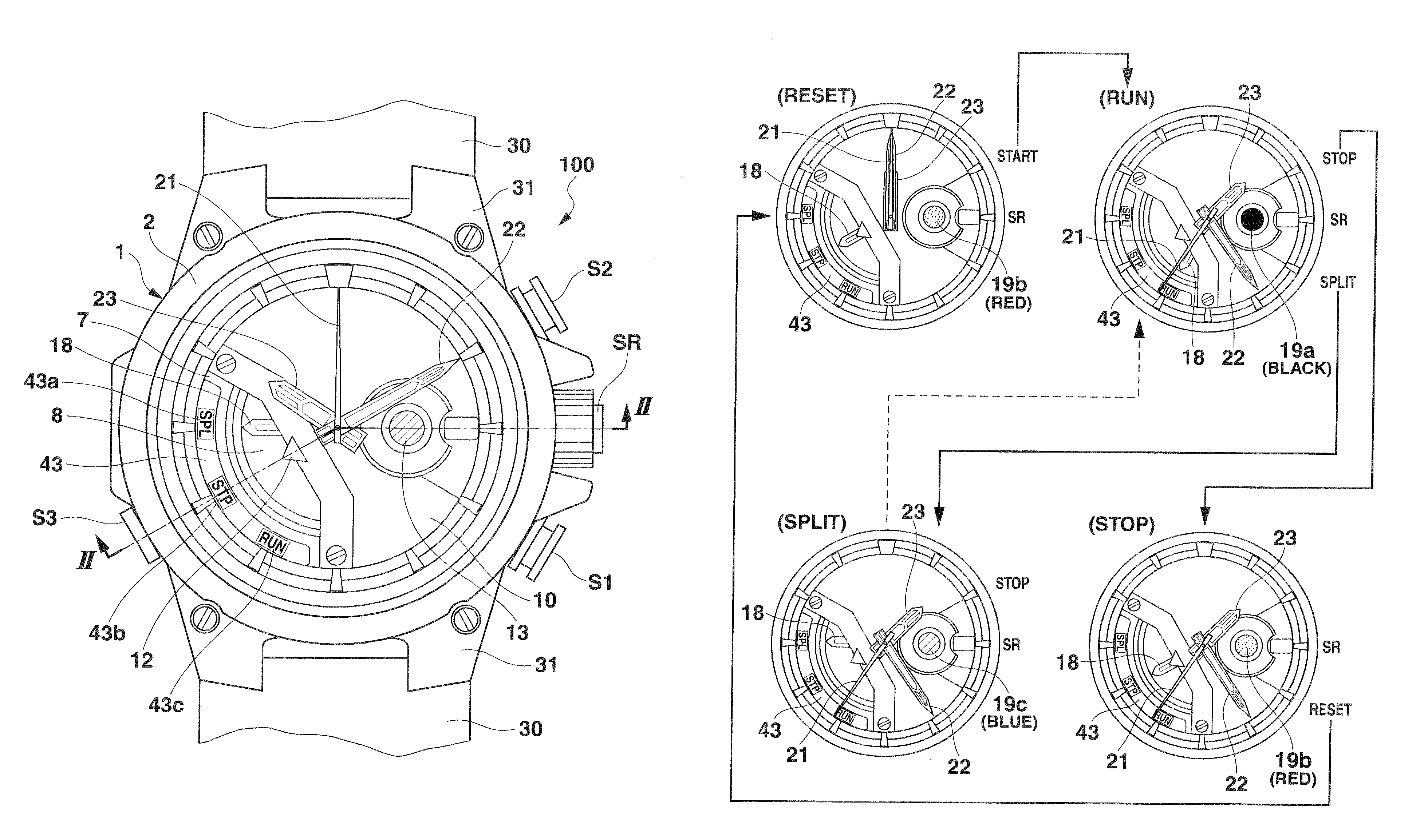
[0020]A watch 100 according to the embodiment is an analog watch having, as shown in FIGS. 1 and 2, a watchcase 1 that constitutes a main body of the watch 100.

[0021]A bezel 2 is attached to an upper portion of an outer periphery of the watchcase 1. A watch glass 3 is attached to an upper periphery of an upper end opening of the watchcase 1 through a gasket 3a. A bottom cover 4 is attached to the bottom of the watchcase 1 through a water-resistant ring 4a. A stem SR and a plurality of push-button switches S1, S2, S3 and the like are provided at a periphery of the watchcase 1.

[0022]The watchcase 1 further includes two fittings 31, 31 for connecting wristbands 30, 30 in directions of twelve o'clock and six o'clock, respectively.

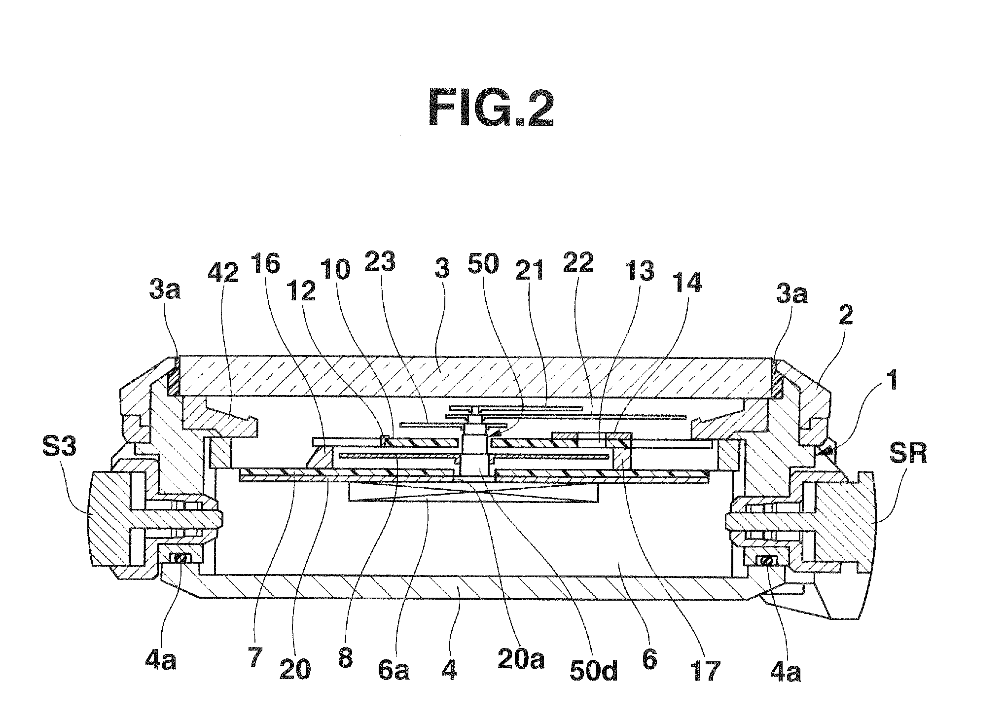
[0023]Further, at an inside of the watchcase 1, there are provided a housing 6 provided with a watch movement 6a, a lower dia...


PUM


Abstract

A dial plate structure includes first and second dial plates, a rotary indicator and a cover member. The first dial plate has a cutout portion. The second dial plate is arranged under the first dial plate and has a plurality of function display portions exposed through the cutout portion. The rotary indicator is arranged between the first and second dial plates and has a function indicator to selectively indicate one of the function display portions by rotation. A part of the rotary indicator is exposed through the cutout portion. The cover member is arranged on the second dial plate. The plurality of function display sections are arranged radially outward than the rotary indicator. The cover member is arranged to face the outer periphery of the rotary indicator and to prevent the outer periphery of the rotary indicator from visually contacted through the cutout portion.

Description

BACKGROUND OF THE INVENTION[0001]1. Field of the Invention[0002]The present invention relates to a dial plate structure and a watch.[0003]2. Description of Related Art[0004]Heretofore, there is known a structure disclosed in Japanese Unexamined Patent Application Publication No. 2009-281961 as a dial plate structure of an analog watch. Concretely, there is known a dial plate structure provided with an upper dial plate having a cutout portion at one part thereof, a sub needle rotatably arranged between the upper dial plate, and a lower dial plate. The lower dial plate has a plurality of function display sections configured to be exposed through the cutout portion, and the sub needle indicates, by a needle tip thereof, one of the plurality of function display sections.[0005]Moreover, there is known a dial plate structure that includes a discoid needle having a function indicator such as an arrow exposed through the cutout portion of the upper dial plate.[0006]By the way, the sub needl...

Claims


Application Information

Patent Timeline
Patent Type & Authority Patents(United States)
IPC IPC(8): G04B19/06
CPCG04B19/065
Inventor SATO, JUNICHI
Owner CASIO COMPUTER CO LTD
Why Eureka
Try Eureka