Electrically conductive structure of micro switch

a micro switch and electrically conductive technology, applied in the direction of electric switches, electrical appliances, contacts, etc., can solve the problems of switch damage, switch rust, and easy rusting of the electrode module and the electrically conductive elastic plate, so as to improve the durability and service life of the micro switch

Inactive Publication Date: 2014-07-08
CHU CHING HSIUNG
View PDF12 Cites 3 Cited by
  • Summary
  • Abstract
  • Description
  • Claims
  • Application Information

AI Technical Summary

Benefits of technology

[0006]Therefore, it is a primary objective of the present invention to overcome the drawbacks of the prior art by provide an the waterproof electrically conductive structure capable of letting user know about the reciprocal movement of a switch button, since the conventional micro switch adopting the electrically conductive elastic plate does not provide a way to let users know about the status of turning on and off the switch, and the conventional micro switch has an interior exposed to the external atmosphere, so that moisture in the atmosphere or external liquid may enter into the switch to cause a poor operation or damage of the switch. The present invention can improve the durability and service life of the micro switch.
[0009]In addition, the top of the base forms a peripheral surface at the external periphery of the containing groove, and the containing groove has a sheath made of a soft high temperature resisting material for covering the axis cylinder, and the external periphery of the sheath is extended to form a circular rib attached onto the peripheral surface for blocking external liquid from entering into the containing groove. Therefore, the containing groove is covered by the circular rib of the sheath to block external moisture or liquid from entering into containing groove, so as to prevent the electrode module and the conductive bump in the containing groove from being rusted.

Problems solved by technology

However, the micro switch adopting the electrically conductive elastic plate does not provide a noticeable means for users to notice the ON and OFF operation, and thus the micro switch adopting the electrically conductive elastic plate cannot be used as the press button of the electronic device or instrument that provides a way to let user know about the reciprocal movement of the switch.
In addition, the containing groove formed on the surface of the base of the conventional micro switch is opened to external atmosphere, so that moisture in the atmosphere or external liquid may enter into the containing groove along the movable shaft easily and affect the operation between the movable shaft, the electrode module and the electrically conductive elastic plate.
As a result, the electrode module and the electrically conductive elastic plate may be rusted easily, and the switch may be damaged or may not be operated properly.

Method used


Image

  • Electrically conductive structure of micro switch
  • Electrically conductive structure of micro switch
  • Electrically conductive structure of micro switch

Examples


Embodiment Construction

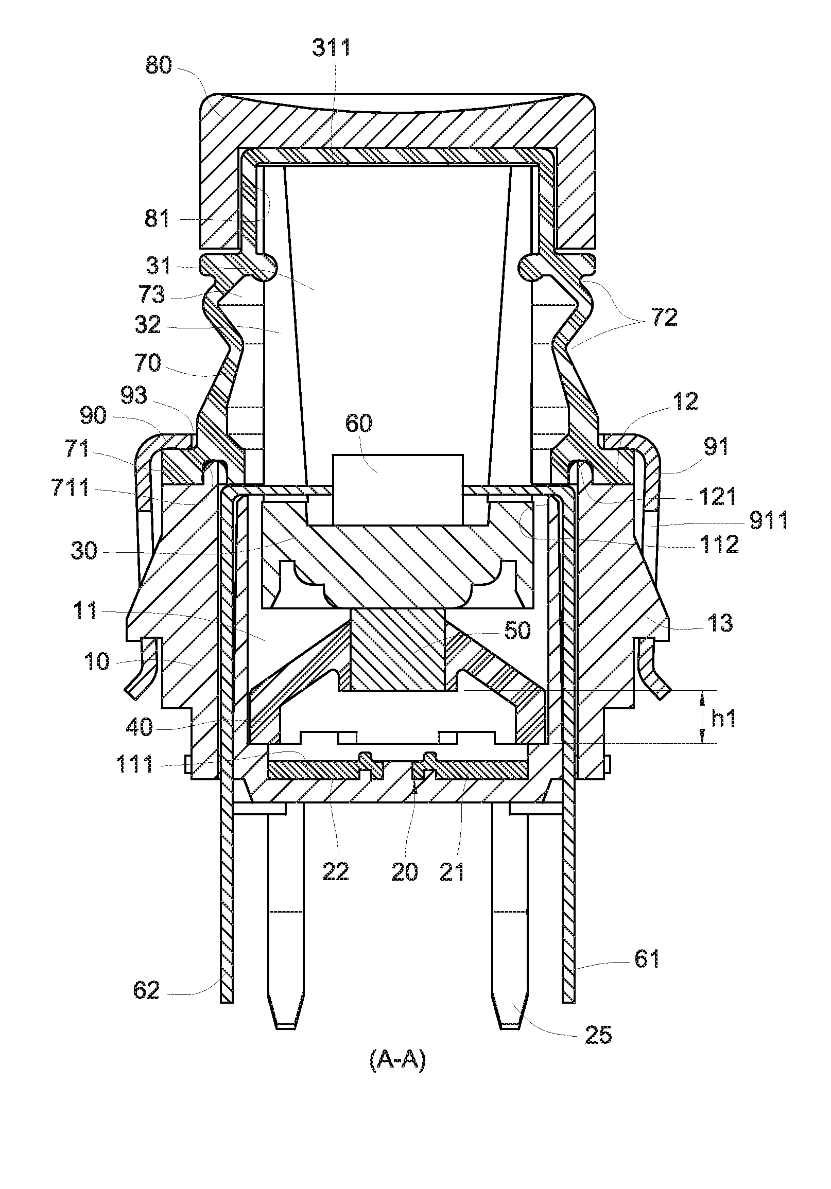
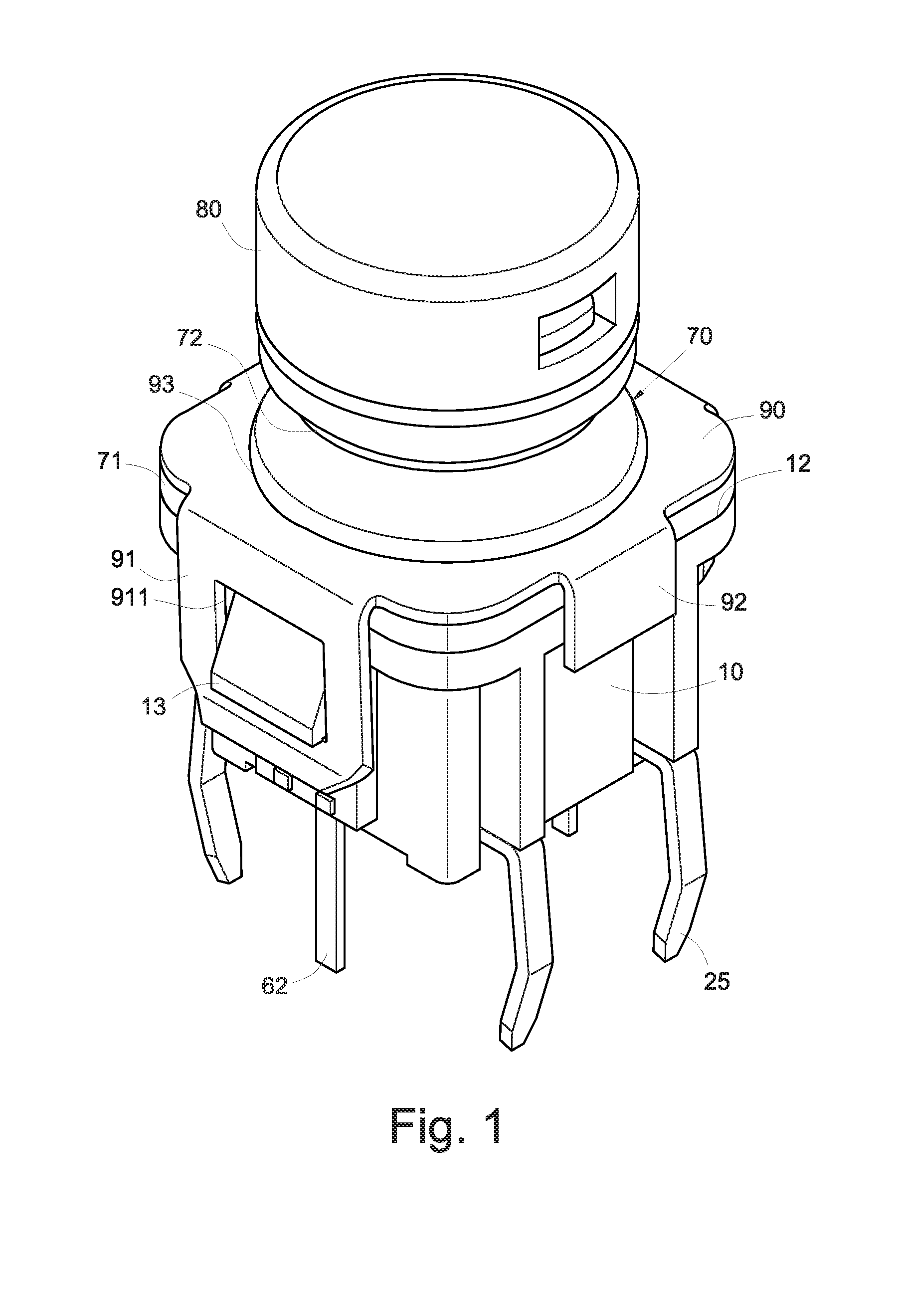
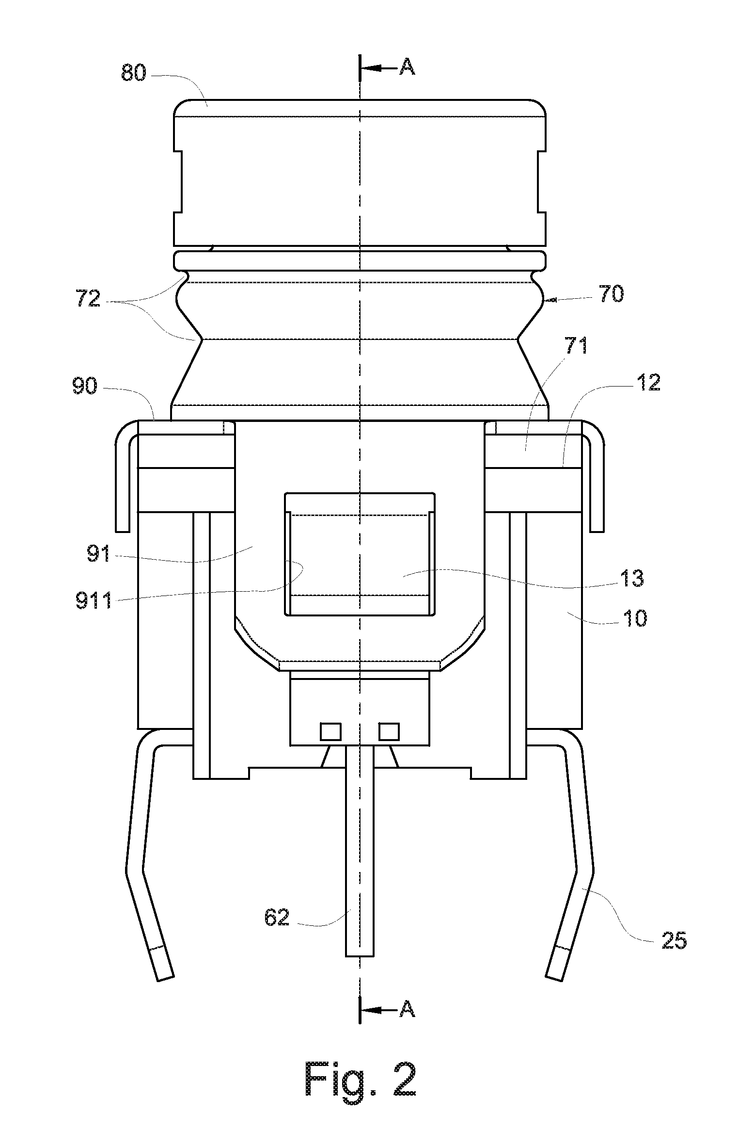
[0022]With reference to FIG. 1 for a perspective view of a preferred embodiment of the present invention and FIGS. 2 to 7 for an electrically conductive structure of a micro switch of the present invention, the electrically conductive structure comprises a rectangular base 10, an electrode module 20, an axis cylinder 30, a conical sleeve 40 with an upwardly tapered diameter and a conductive bump 50, wherein the base 10 has a containing groove 11 formed at the top of the base 10, and a peripheral surface 12 formed at the external periphery of the containing groove 11; the electrode module 20 is disposed at a groove bottom 111 at the bottom of the containing groove 11, and the electrode module 20 includes a positive electrode 21 and a negative electrode 22 with electrically conductive terminal 25 extended to the bottom of the base 10, and the electrically conductive terminal 25 are extended to both sides of the bottom of the base 10.

[0023]The bottom of the axis cylinder 30 is slidably...


PUM


Abstract

An electrically conductive structure of a micro switch capable of letting users know about the reciprocal movement of a switch button, comprising a base, having an electrode module installed in a containing groove formed at the top of the base; an axis cylinder slidably installed in the containing groove; a conical sleeve made of a soft high temperature resisting material and disposed between the axis cylinder and the electrode module; a metal conductive bump formed at the top of the conical sleeve and driven by the axis cylinder to compress and release the conical sleeve to connect and disconnect the electrode module, and the axis cylinder moves reciprocally to produce a hand-pressing feeling, and the containing groove has as sheathe made of a soft high temperature resisting material to block external liquid from entering into the containing groove to improve the service life of the switch.

Description

FIELD OF THE INVENTION[0001]The present invention relates to an electrically conductive structure of a micro switch, in particular to the waterproof electrically conductive structure capable of letting users know about the reciprocal movement of a switch button, and the electrically conductive structure involves a containing groove of a base of the switch, internal and external electrode modules of the containing groove axis cylinder, and a waterproof sheath, particularly involves a conical sleeve and a conductive bump in the containing groove.BACKGROUND OF THE INVENTION[0002]Various types of electronic switches come with different sizes and specifications, the scope of applicability is very broad, and general precision equipments, small equipments or electric appliances usually use an electronic switch, and most electronic switches are smart switches, micro switches and touch switches. Since these types of switches have a light, thin, short and compact design, therefore they can be...

Claims


Application Information

Patent Timeline
Patent Type & Authority Patents(United States)
IPC IPC(8): H01H1/52
CPCH01H13/023H01H13/063H01H13/06H01H13/26H01H2013/066
Inventor CHU, CHING-HSIUNG
Owner CHU CHING HSIUNG
Why Eureka
Try Eureka