Power flow measurement and management

a technology of power flow and measurement, applied in the direction of dc source parallel operation, transmission system, electric variable regulation, etc., can solve the problems of imposing a burden on providers, power flows relating to individual devices at a given premises, or a group of devices distributed across multiple premises, and it is prohibitive to install a separate meter at each power consuming and/or providing uni

Active Publication Date: 2014-11-18
REACTIVE TECH
View PDF31 Cites 4 Cited by
  • Summary
  • Abstract
  • Description
  • Claims
  • Application Information

AI Technical Summary

Benefits of technology

[0011]By controlling the power flow at a power unit according to a predefined power flow pattern, a measurement node in a network to which the unit is connected having access to the pattern can detect and measure the power flow resulting from the power unit, allowing the power flow to be remotely detected and measured. Further, since the method requires only that power flow to and / or from a power unit be controlled (for example, switched on and off), it does not require complicated and expensive measuring equipment, such as a smart meter.
[0013]In some embodiments, the method comprises preventing power flow to and / or from the power unit in response to a deactivation signal. Thus, power units can be turned off centrally, allowing central control of power flow in the network.
[0024]Preferably, the predefined power flow pattern comprises a repeating pattern, and the power flow control devices are configured to controlling power to and / or from the group of one or more power units continuously according to the repeating pattern. The method of the present invention allows continuous measurement of power consumption of a power unit, in contrast to prior art methods, which generally provide only intermittent measurement.
[0037]This provides a convenient method of defining groups for use in measurement methods according to aspects of the present invention; by iterating the measurement and modification steps, it can be assured that groups having appropriate characteristics are defined.

Problems solved by technology

Since it is expensive to store electricity in large quantities, it is usually generated when it is required, which can place a burden on providers as they attempt to meet demand at peak times.
This means that power flows relating to individual devices at a given premises, or a group of devices distributed across multiple premises, cannot easily be measured, particularly in view of the relatively high cost of smart meters making it prohibitive to install a separate meter at each power consuming and / or providing unit to be measured.

Method used


Image

  • Power flow measurement and management
  • Power flow measurement and management
  • Power flow measurement and management

Examples


Embodiment Construction

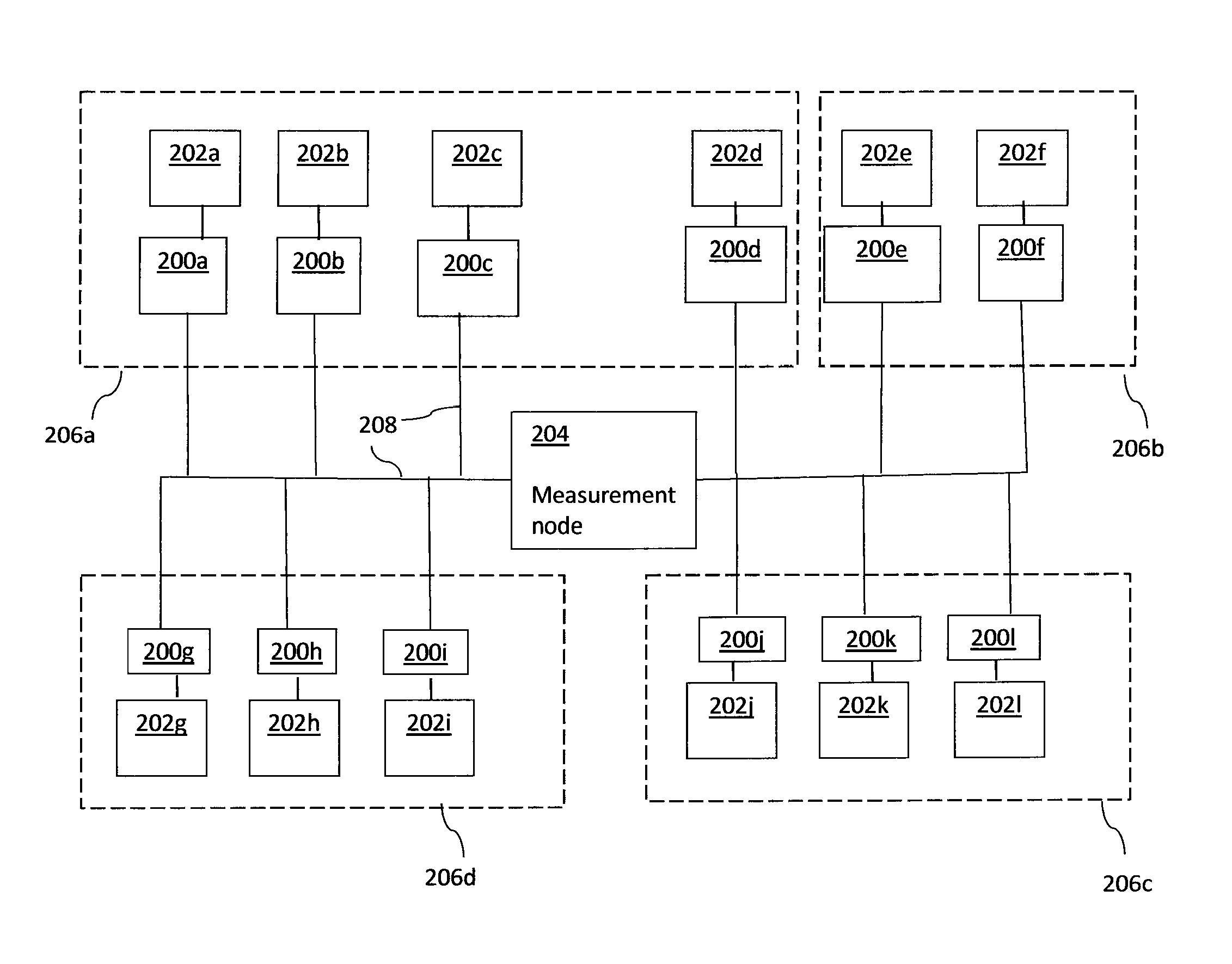
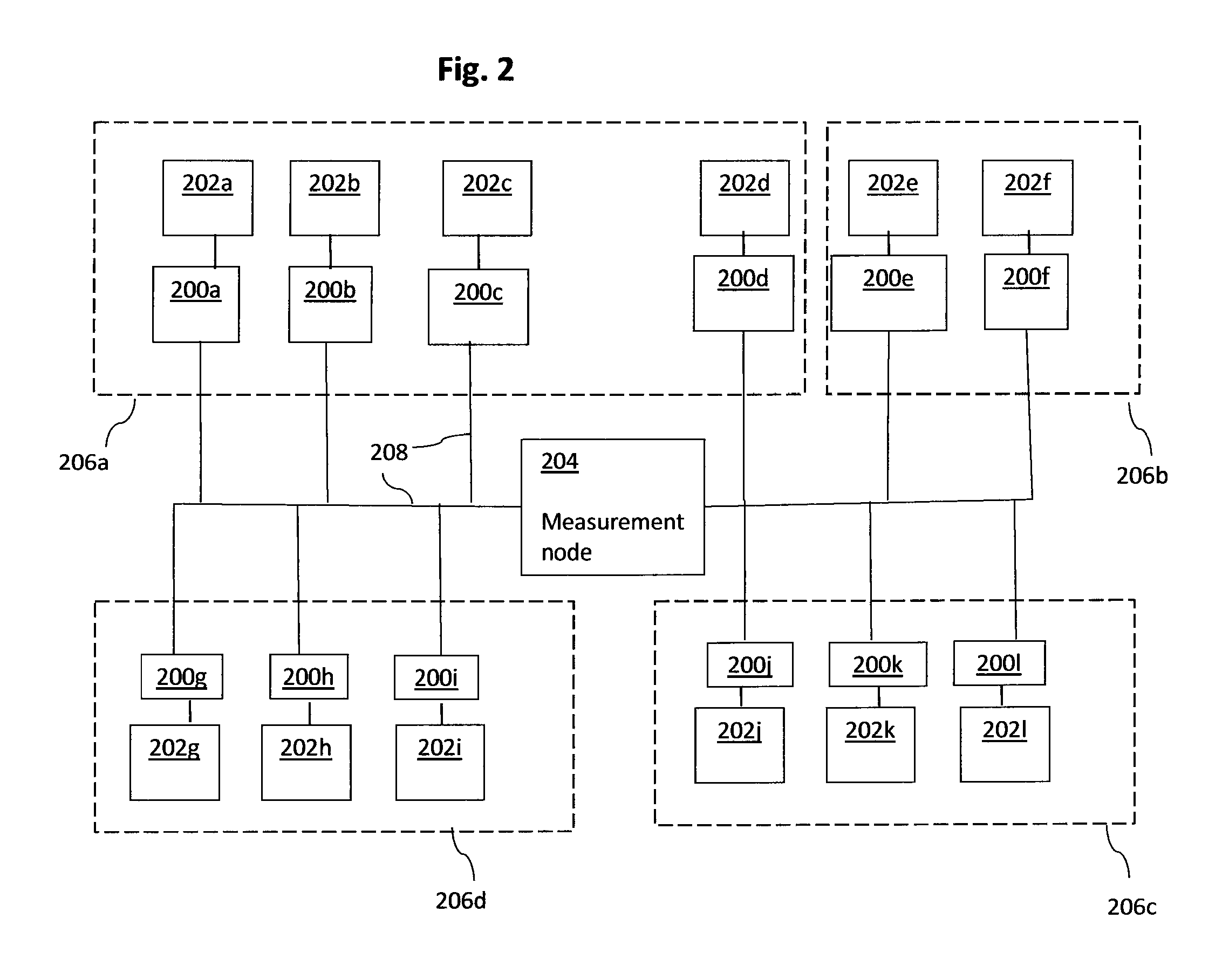
[0054]FIG. 2 illustrates an electricity distribution network in which an embodiment of the present invention may be implemented. The network comprises a measurement node 204 which is connected via power lines 208 to power units 202a to 202l via power flow control devices 200a to 200l. Each of the power units 202a to 202l consumes and / or provides electric power. Examples of power units consuming electric power include domestic appliances such as electric water heaters and washing machines, as well as industrial devices, such as factory machinery and desktop computers. Examples of providers of electric power include solar panels and wind-turbines. Still other power units may consume electric power at some times but provide it at others, such as the PEVs described above. Further, the term power unit is used herein to include collections of such appliances and devices, such as a house. Each of the power units is associated with a power flow control device 200a to 200l, which controls tr...


PUM


Abstract

Methods and systems for measuring and / or managing power consumption by power units connected to an electricity distribution network are disclosed. Power flow to and / or from a power unit connected to an electricity distribution network is controlled in accordance with a control sequence, such that the consumption and / or provision of power by the power unit results in a power flow having a predefined flow pattern, and having a characteristic, such as an amplitude, which can be remotely measured. This measurement may be performed using a method in which a signal indicative of power flowing at a measurement node is measured and correlated with a predefined pattern, and a characteristic of the correlated signal is measured. Thus, power flow characteristics resulting from a group of one or more power flow devices can be remotely detected and measured.

Description

CROSS-REFERENCE TO RELATED APPLICATION[0001]The present application claims priority under 35 USC 119 of UK Patent Application GB 1001397.7 filed Jan. 28, 2010, the entire disclosure of which is incorporated herein by reference.FIELD OF THE INVENTION[0002]The present invention relates to management of power flow in an electricity distribution network. In particular, but not exclusively, it relates to measurement of power consumption and provision by power units connected to the network.BACKGROUND OF THE INVENTION[0003]Supply of electricity from providers such as power stations, to consumers, such as domestic households and businesses, typically takes place via an electricity distribution network. FIG. 1 shows an exemplary distribution network comprising a transmission grid 100 and a distribution grid 102. The transmission grid is connected to generating plants 104, which may be nuclear plants or gas-fired plants, for example, from which it transmits large quantities of electrical ene...

Claims


Application Information

Patent Timeline
Patent Type & Authority Patents(United States)
IPC IPC(8): H02J3/06G05D3/12
CPCH02J3/06Y10T307/391G05F1/66G01R21/005H02J3/00H02J13/0006
Inventor HUOMO, HEIKKI
Owner REACTIVE TECH
Why Eureka
Try Eureka