Water-carrying domestic appliance having a water-distribution mechanism

Active Publication Date: 2014-12-23
BSH BOSCH & SIEMENS HAUSGERAETE GMBH
View PDF11 Cites 26 Cited by
  • Summary
  • Abstract
  • Description
  • Claims
  • Application Information

AI Technical Summary

Benefits of technology

[0009]The invention has the advantage that it is possible in a particularly simple manner reliably to seal a transition region between a rotatable fluid distribution element formed by a flat rotating disk, to which a fluid to be discharged to one or more fluid discharge lines can be supplied from a fluid supply line, and the inlet region of the relevant fluid discharge lines, in that the respective passage openings are configured as Venturi openings so that the fluid pressure of the fluid flowing through the transition region between the outlet side of the respective passage opening and the inlet region into the respective fluid discharge line in each instance is lower than the pressure in the region surrounding the relevant transition region. This ensures that no fluid exits from the passage openings into the surrounding region in the abovementioned transition region. It is also advantageous that the sealing apparatus according to the present invention has absolutely no need for mechanical sealing bodies or elements, which would anyway be difficult—or even impossible—to realize in the case of a rotatable fluid element configured as a flat rotating disk. Also the present invention makes it possible in a relatively simple manner for the relevant fluid distribution element to be able to dispense the fluid with a smaller pressure loss than with the known water diverters considered in the introduction.
[0010]To make particularly effective use of the possibility offered by the present invention of the relevant fluid distribution element being able to dispense the fluid with a smaller pressure loss than with the known water diverters considered in the introduction, the passage openings in the rotating disk in the apparatus according to the present invention are expediently aligned in relation to the fluid supply line and to the fluid discharge lines in each instance so that the fluid flow directions into and out of the passage openings run respectively in the axial direction of the rotating disk. This has the advantage of a part

Problems solved by technology

However such a mechanical sealing apparatus is only suitable for a seal in a cylindrical housing.
The known mechanical sealing apparatus in question is not suitable for sealing passage openings through a flat rotating disk in respect of fluid discharge lines opposite said flat rotating disks.
Also this known water diverter can produce an unwanted pressure loss in the water flow to be distributed in each instance due to its deflection by means of the swivel tube.
However this

Method used


Image

  • Water-carrying domestic appliance having a water-distribution mechanism
  • Water-carrying domestic appliance having a water-distribution mechanism
  • Water-carrying domestic appliance having a water-distribution mechanism

Examples


Example

[0023]Before examining the drawings in more detail, it should be noted that identical elements and facilities are shown with the same reference characters in all the figures.

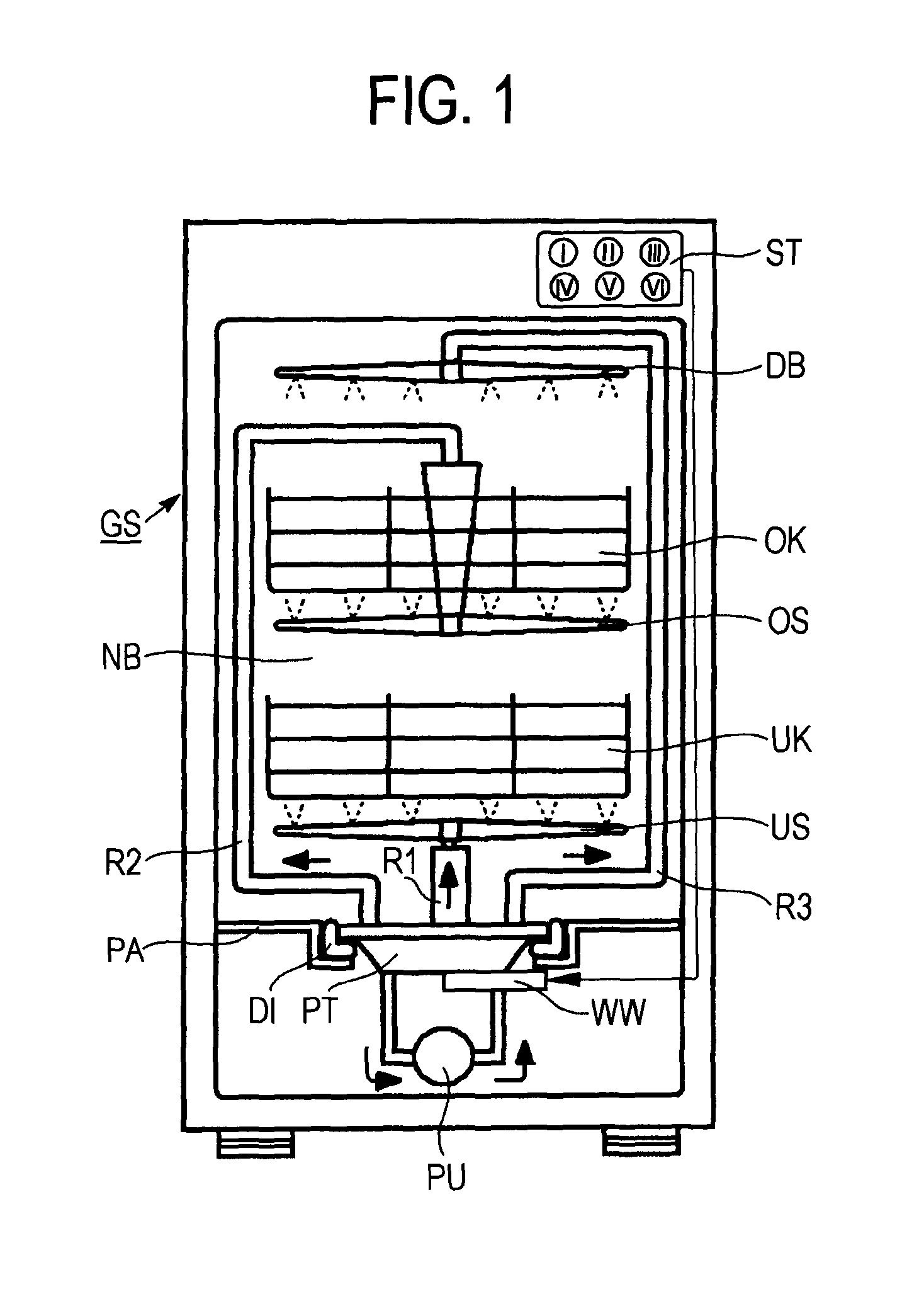
[0024]The schematic diagram in FIG. 1 shows a dishwasher GS with sufficient detail for an understanding of the present invention. The dishwasher GS contains a preferably closeable wash container, which has a wet region NB according to FIG. 1. In this wet region NB is at least one rack—in the present instance in fact two racks are provided, namely a lower rack UK and an upper rack OK disposed above it. A lower spray arm US is disposed below the lower rack UK, allowing washing liquor to be dispensed from its upper face onto the lower rack UK and items to be washed that may be contained therein—as shown by spray jets. While dispensing this washing liquor the lower spray arm US rotates in the known manner due to the water pressure of the washing liquor dispensed by it. An upper spray arm OS is disposed above the low...


PUM


Abstract

A water-carrying domestic appliance, especially a dishwasher or washer, which comprises a water diverter having at least one adjustable fluid distribution element, to which a fluid to be discharged through one or more fluid discharge lines can be supplied from a fluid supply line. In an exemplary embodiment of the invention, the fluid distribution element includes a plurality of passage openings respectively configured as funnel-shaped for sealing purposes such that a fluid pressure of the fluid flowing through a transition region between an outlet side of a respective passage opening and an inlet region into a respective fluid discharge line is lower than a pressure in a region surrounding the transition region.

Description

BACKGROUND OF THE INVENTION[0001]Water diverters are used in water-bearing domestic appliances, such as washing machines or dishwashers for example, to control flows of liquid in the water-bearing domestic appliance. When used in a washing machine water diverters serve to dispense washing or rinsing water for example to a first or second detergent compartment of two detergent compartments. When used in dishwashers water diverters serve to dispense washing water, also referred to as washing liquor, for example alternately to a spray arm for an upper rack or to a spray arm for a lower rack of the respective dishwasher or simultaneously to both spray arms.[0002]In the case of a known water diverter (DE 16 10 146 B2) a rotatable control slider is provided in a cylindrical housing, connecting a supply channel to one of a number of discharge channels by means of a swivel tube. The swivel tube here has a rotating pin, which is disposed in a socket of the supply channel in the manner of a b...

Claims


Application Information

Patent Timeline
IPC IPC(8): A47L15/42D06F39/02
CPCD06F39/028A47L15/4221Y10T137/87909
Inventor BUSING, JOHANNESOBLINGER, ANTONSANCHO, PEDROSEMERAD, DAVIDSTICKEL, MARTIN
Owner BSH BOSCH & SIEMENS HAUSGERAETE GMBH
Why Eureka
Try Eureka