Elongated structure for movable section

a technology of movable sections and elongated structures, which is applied in the direction of insulating conductors, cables, and relatively moving parts, etc., can solve the problems of disordered movement of cables and tubes, etc., and achieve the effect of enlargement of attachment strength

Active Publication Date: 2015-02-10
DAIDEN CO LTD
View PDF19 Cites 7 Cited by
  • Summary
  • Abstract
  • Description
  • Claims
  • Application Information

AI Technical Summary

Benefits of technology

[0009]As mentioned above, in the present invention, the operational linear elements, such as electric wires, optical cables and so on, through which electricity, light and so on are transmitted as the operational factors, and such as tubes, pipes and so on, through which air, hydraulic oil and so on are transmitted as the operational factors, are provided in the sheath member so as to be extended from one end of the sheath member to the other end thereof, and are arranged in parallel in the sheath member. The rigidity of the outer region of the sheath member is larger than that of the inner region which is defined as an inner side when the sheath member is bent. Thus, when the sheath member has the regions exhibiting the different rigidities, and when an external force is exerted on the elongated structure for the movable section, it is apt to bend toward the side of the sheath member having the small rigidity, and the bent portion is maintained at a given curvature which is determined by the entire rigidity of the elongated sheath member. Therefore, the elongated structure for the movable section cannot easily meander while the movable end thereof is moved. Also, while the position of the bent portion is shifted, it is possible to stably carry out the movement of the movable end and the shift of the bent portion. In addition, a protective guide structure is not needed, and not only can an installing space for the elongated structure for the movable section become smaller, but also it is possible to cut down a cost necessary for such a protective guide structure. Further, while the sheath member containing the operational linear elements is moved a predetermined area, it is possible to suppress generation of motes and creation of noises as small as possible. Note, an adjustment of the rigidity of the sheath member by either a difference between the thickness of the inner region and the thickness of the outer region or a difference between the rigidity of the inner region and the rigidity of the outer region.
[0031]As stated above, in the present invention, in the case where the sheet member is intervened between the plurality of block members and the cable member(s), the cable member(s) is united with the sheet member, and the block members can be closely contacted with the sheet member. Thus, after the block members and the cable member(s) are individually produced, when the block members and the cable member(s) are united with each other, it is possible to obtain the maximum contact area between the sheet member and the block members so that the block members are strongly united with the sheet member. If the cable member(s) and the block members are directly united with each other, it is impossible to obtain a sufficient contact area between the cable member(s) and the block members, and thus an enough attachment strength cannot be expected. Nevertheless, the block members can be closely contacted with the sheet member with the sufficient contact area. Thus, it is possible to obtain a large adhesive between the sheet member and the block members, so that the block members can be adhered with a suitable adhesive strength to the sheet member. As a result, the block members and the cable member(s) can be strongly united with each other, and thus it is possible to use the elongated structure for the movable section without any problems.

Problems solved by technology

Nevertheless, the cables and tubes having flexibility can be disorderly moved, and the disorder movement of the cables and tubes may be a hindrance to an operation of the industrial apparatus.

Method used


Image

  • Elongated structure for movable section
  • Elongated structure for movable section
  • Elongated structure for movable section

Examples


first embodiment

of the Invention

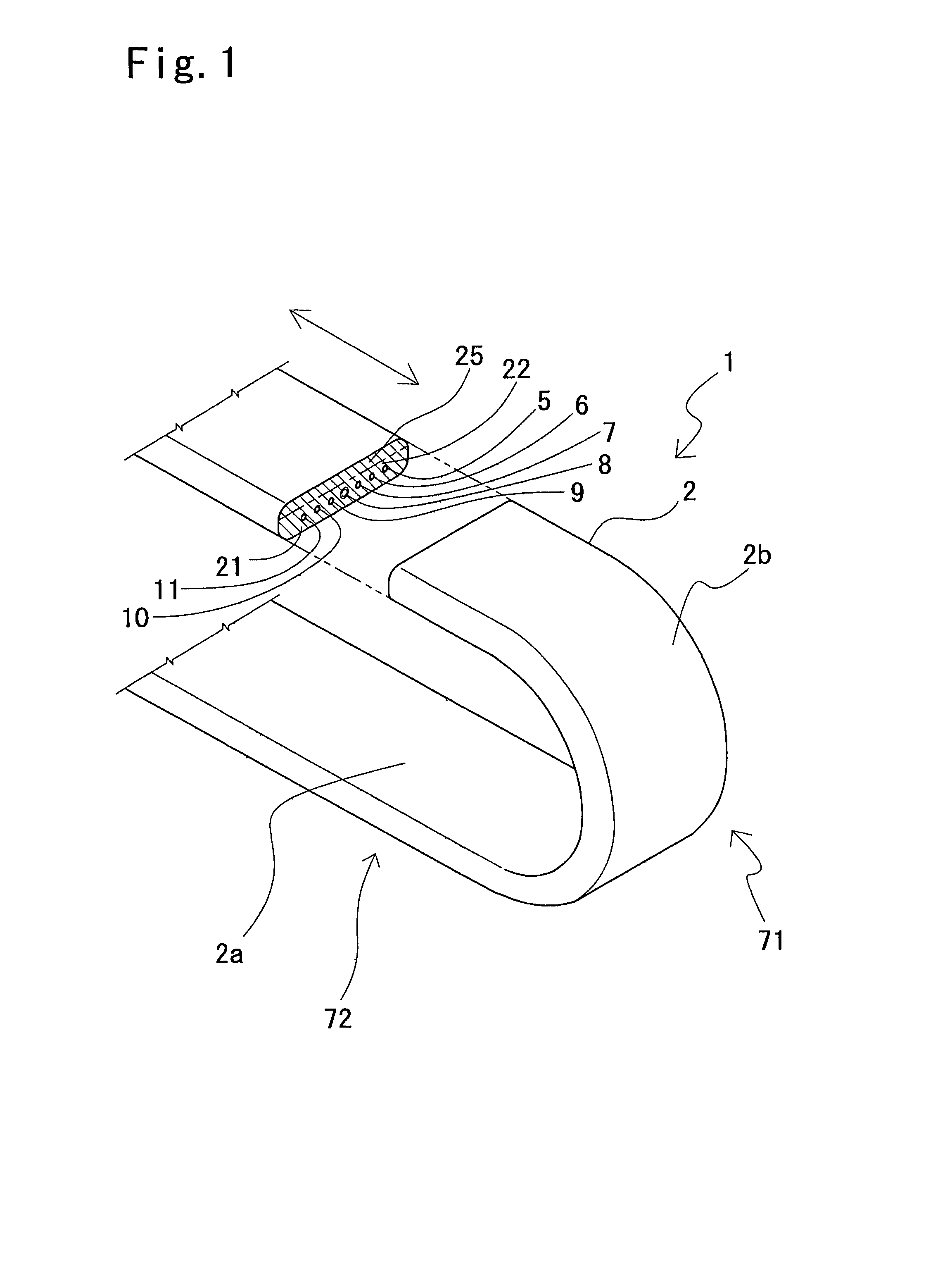
[0045]With reference to FIG. 1, an elongated structure for a movable section according to the first embodiment of the present invention will now be explained below.

[0046]In FIG. 1, the elongated structure 1 for the movable section includes a sheath member 2 which is formed as an elongated flexible member, and a plurality of operational flexible linear elements 5, 6, 7, 8, 9, 10 and 11 which are provided in the sheath member 2 so as to be extend from one end of the sheath member 2 from the other end thereof, and through which operational factors are transmitted.

[0047]The aforesaid sheath member 2 has an elongated flat belt-like configuration having a suitable thickness, and the operational linear elements 5, 6, 7, 8, 9, 10 and 11, such as conductor wires, tubes and so on for transmitting the operational factors such as electricity, air and so on, are arranged widthwise in the sheath member 2 in parallel so as to be spaced away from each other. The sheath member 2 is f...

second embodiment

of the Invention

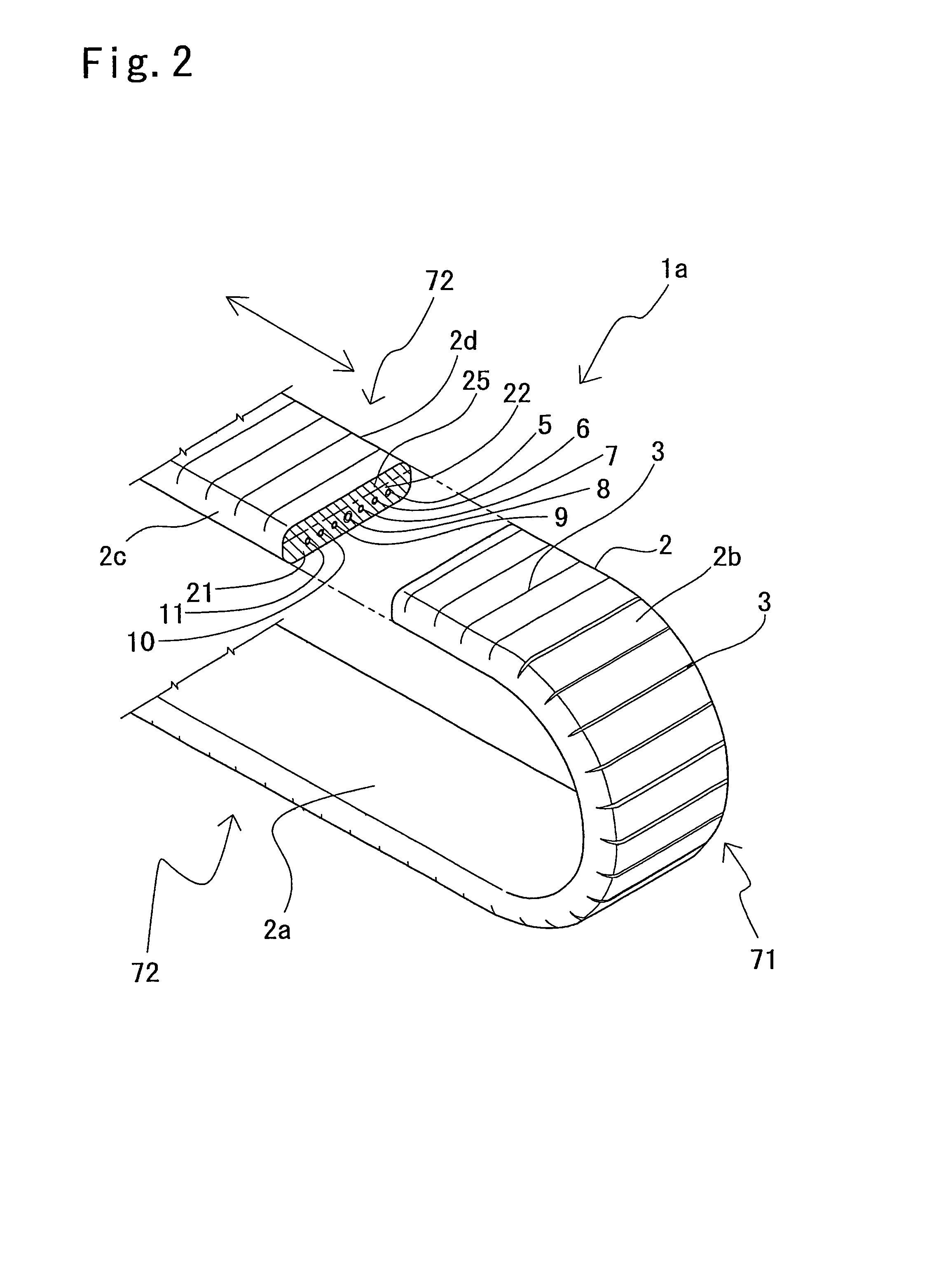
[0062]With reference FIG. 2 a second embodiment of the present invention will now be explained. As shown in FIG. 2, in an elongated structure 1a for a movable section, a plurality of slits 3 are provided in a sheath member 2. Note, in FIG. 2, the same references as in FIG. 1 indicate the corresponding elements, and explanations of these elements are omitted.

[0063]As shown in FIG. 2, the plurality of slits 3 are formed in a surface 2b of an outer region of the sheath member 2, which is defined as an outer surface, at given regular intervals in a longitudinal direction of the sheath member 2 so as to be extended from one side face 2c of the sheath member 2 to the other side face 2d through the outer surface 2b thereof. Some of the slits 2 are opened in a U-shaped bent portion 71 of the elongated structure 1a for the movable section, and the remaining slits 3 are closed in linear portions 72 thereof except for U-shaped bent portion 71. Thus, when forces for bending the ...

third embodiment

of the Invention

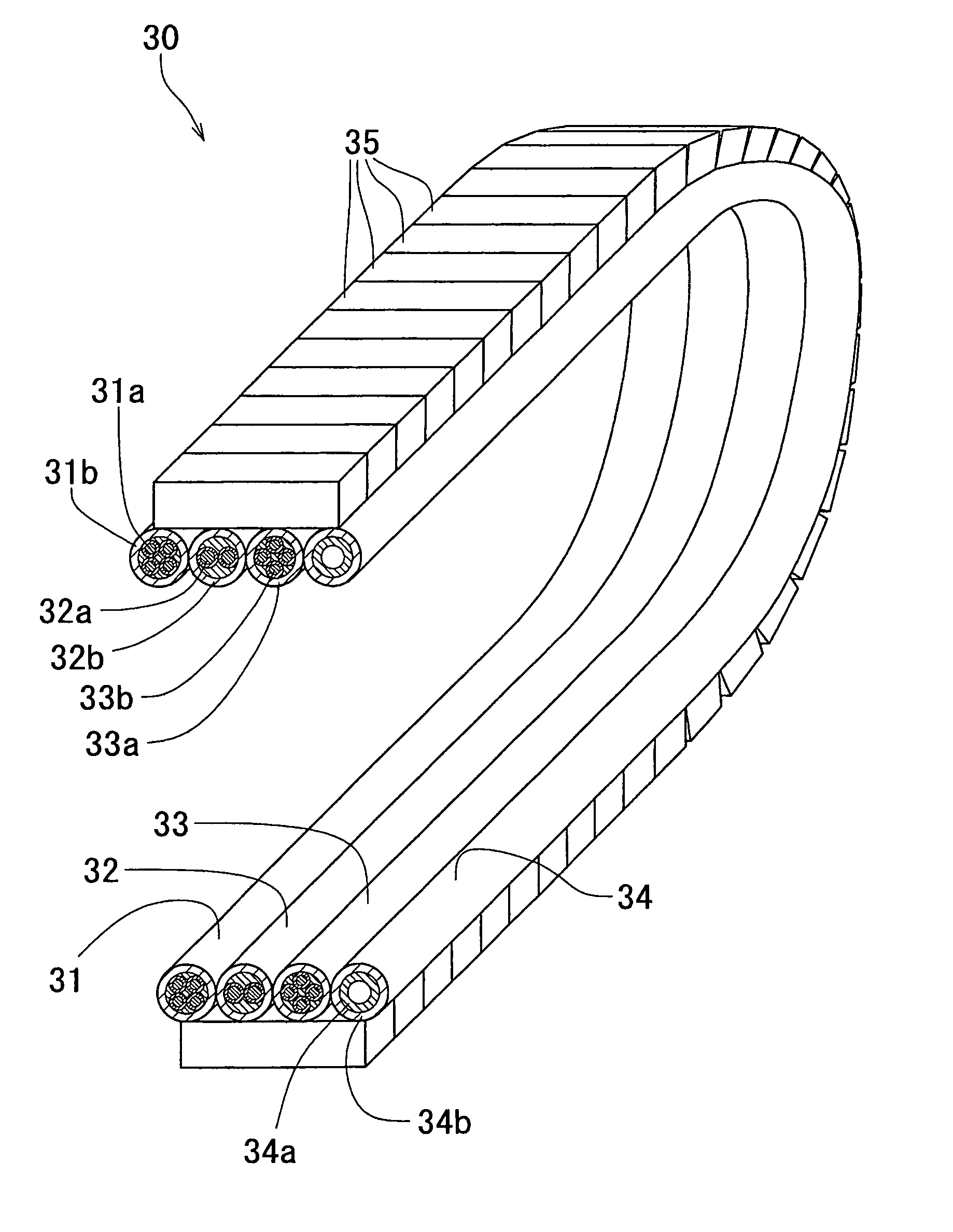
[0068]With reference to FIG. 3, a third embodiment of the present invention will now be explained. As shown in FIG. 3, an elongated structure 1b for a movable section has a flat belt-like configuration in which a plurality of sheath members 20 are arranged in parallel and securely attached to each other.

[0069]As shown in FIG. 3, each of the sheath members 20 has generally-oval end faces, and these sheath members 20 are arranged so that the major axes in the generally-oval end faces are parallel to each other. Operational flexible linear elements 5, 6, 7, 8, 9, 10 and 11 are provided in the respective sheath members 20 so that the center of each of the operational linear elements 5, 6, 7, 8, 9, 10 and 11 is offset from the center of the major axis of a corresponding sheath member 2 toward one end 20a of the major axis by a predetermined distance. Thus, a thickness of an outer region 22, which is measured from the other ends 20b of the major axes, defined as the outer ...


PUM

PropertyMeasurementUnit
lengthaaaaaaaaaa
outer diameteraaaaaaaaaa
thicknessaaaaaaaaaa

Abstract

In an elongated structure for a movable section, a plurality of operational linear elements such as conductive wires are arranged in parallel in a belt-like sheath member, and an outer region of the sheath member, which is defined by a bend of the sheath member, has a larger rigidity than that of an inner region of the sheath member, which is defined by the bend of the sheath member. When the sheath member 2 have the regions exhibiting the different rigidities, and when an external force is exerted on the elongated structure 1 for the movable section, it is apt to bend toward the side of the sheath member having the small rigidity, and the bent portion is maintained at a given curvature which is determined by the entire rigidity of the sheath member 2. Therefore, the elongated structure 1 for the movable section cannot easily meander while the movable end thereof is moved. Also, while the position of the bent portion is shifted, it is possible to stably carry out the movement of the movable end and the shift of the bent portion. In addition, a protective guide structure is not needed, and not only can an installing space for the elongated structure 1 for the movable section become smaller, but also it is possible to cut down a cost necessary for such a protective guide structure.

Description

TECHNICAL FIELD[0001]The present invention relates to an elongated structure for a movable section, which is provided in an apparatus including a movable section, such as a mounting apparatus, an industrial robot and so on, and which contains linear conductors or the like.BACKGROUND ART[0002]In a mounting apparatus for mounting electronic parts on a board in place, a chuck mechanism for holding an electronic part is movable in both widthwise and lengthwise directions. In order to drive the chuck mechanism, a base of the chuck mechanism and a main body of the mounting apparatus are connected to each other by cables feeding electric power and control signals and tubes for feeding air and hydraulic oil. In this mounting apparatus, while the base of the chuck mechanism is moved in widthwise direction, the cables and tubes must follow the moving base. In industrial apparatuses including the mounting apparatus, cables, tubes and so on are provided between movable and fixed sections of an ...

Claims


Application Information

Patent Timeline
Patent Type & Authority Patents(United States)
IPC IPC(8): F16L3/08H01B7/04H01B7/08H02G11/00
CPCH01B7/0823H02G11/006H01B7/041
Inventor IKEDA, DAISUKEKAWANAMI, YASUAKITERASAKI, KOUJI
Owner DAIDEN CO LTD
Why Eureka
Try Eureka