Exhaust treatment apparatus for engine

a technology for exhaust gas treatment and engine, which is applied in the direction of mechanical equipment, engines, machines/engines, etc., can solve the problems of poor continuance of combustion poor continuous combustion flame of combustible gas, so as to improve the continuance of combustion flame, facilitate the development of combustion flame, and improve the effect of combustion flam

Active Publication Date: 2015-12-01
KUBOTA LTD
View PDF11 Cites 0 Cited by
  • Summary
  • Abstract
  • Description
  • Claims
  • Application Information

AI Technical Summary

Benefits of technology

[0020]In the improper overlaid state, at least two components out of the overlaid components (52), (47) and (53) are not closely attached to each other. Thus, erroneous assembly of the components can be suppressed. Thus, improper orientation or positioning of the exhaust guiding plate (46) or the gaskets (52) and (53) can be suppressed.
[0021]The invention according to claim 3 provides the following effect in addition to the effect provided by the invention according to claim 2.
[0023]Even when the components are in the proper overlaid state, in the improper clamped state, one of the exhaust upstream side component (50) and the exhaust downstream side component (51), and the components (52), (47), and (53) in the proper overlaid state are not closely attached to each other. Thus, erroneous assembly of the components would not possibly occur. Thus, orientation or positioning of the exhaust guiding plate (46) or the gaskets (52) and (53) becomes proper.
[0026]As illustrated in FIGS. 1A and 1B, the function of preventing erroneous assembly of the components achieves the following. When the components (52), (47) and (53) in the proper overlaid state are clamped between the exhaust upstream side component (50) and the exhaust downstream side component (51) in the proper clamped state, the liquid sealing-out layer (53e) is closely attached to the exhaust downstream side component (51), and a liquefied product of the combustible gas (2) that accumulates in an upstream side in the combustible gas supplying passage (8) from the flame holding plate (42) is sealed out by the liquid sealing-out layer (53e). Accordingly, sealability of the liquid sealing-out layer (53e) is secured.
[0024]The invention according to claim 4 provides the following effect in addition to the effects provided by the invention according to claim 2 or 3.
[0025]Sealability of the liquid sealing-out layer is secured.
[0027]The invention according to claim 5 provides the following effect in addition to the effects provided by the invention according to any of claims 2 to 4.
[0030]The invention according to claim 6 provides the following effect in addition to the effects provided by the invention according to any of claims 1 to 5.
[0013]Continuance of combustion flame of combustible gas can be improved.
[0032]As illustrated in FIG. 6, since the exhaust gas blocking walls (60) and (60) are formed on the opposite sides of the folding edge (58) of the exhaust guiding plate (46), the exhaust (6) does not enter the area surrounding the ignition apparatus (10) from the opposite sides of the folding edge (58) of the exhaust guiding plate (46), and continuance of combustion flame of the combustible gas (2) can be improved.

Problems solved by technology

However, this conventional technique involves a problem since the ignition apparatus is exposed to the exhaust passage from beneath.
Continuance of combustion flame of combustible gas is poor.
Accordingly, exhaust tends to blow off combustion flame of combustible gas, and thus continuance of combustion flame of combustible gas is poor.

Method used


Image

  • Exhaust treatment apparatus for engine
  • Exhaust treatment apparatus for engine
  • Exhaust treatment apparatus for engine

Examples


Embodiment Construction

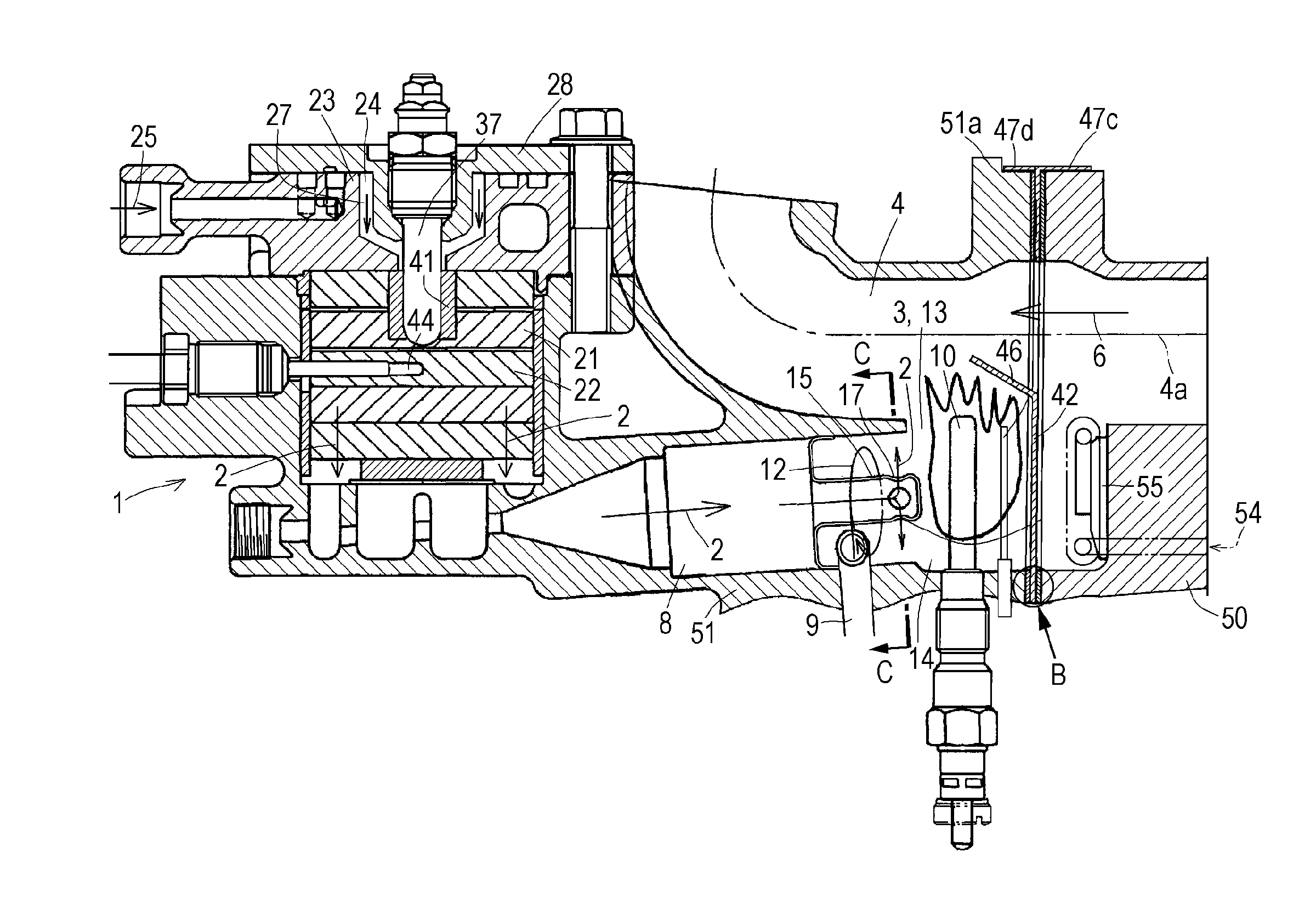
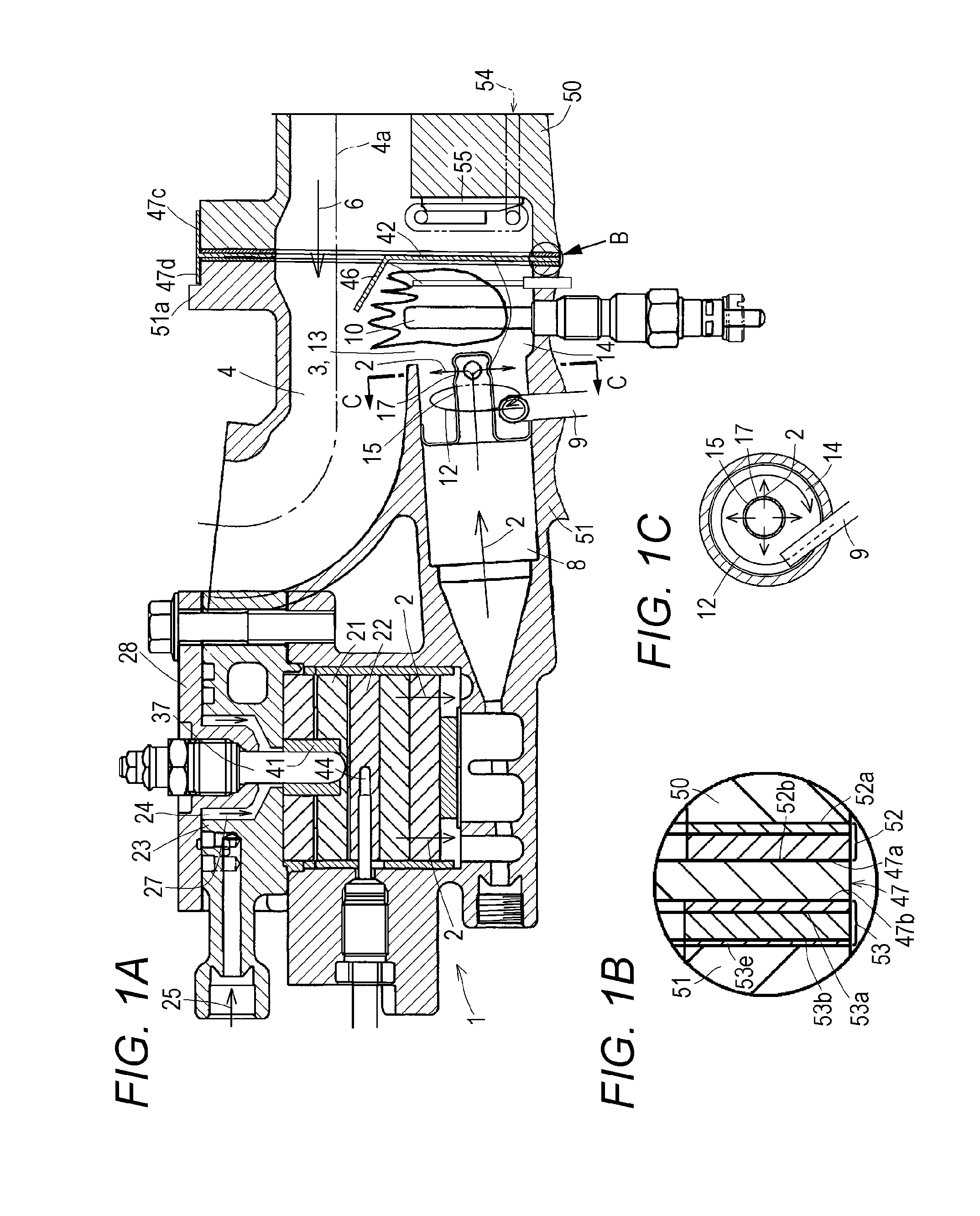
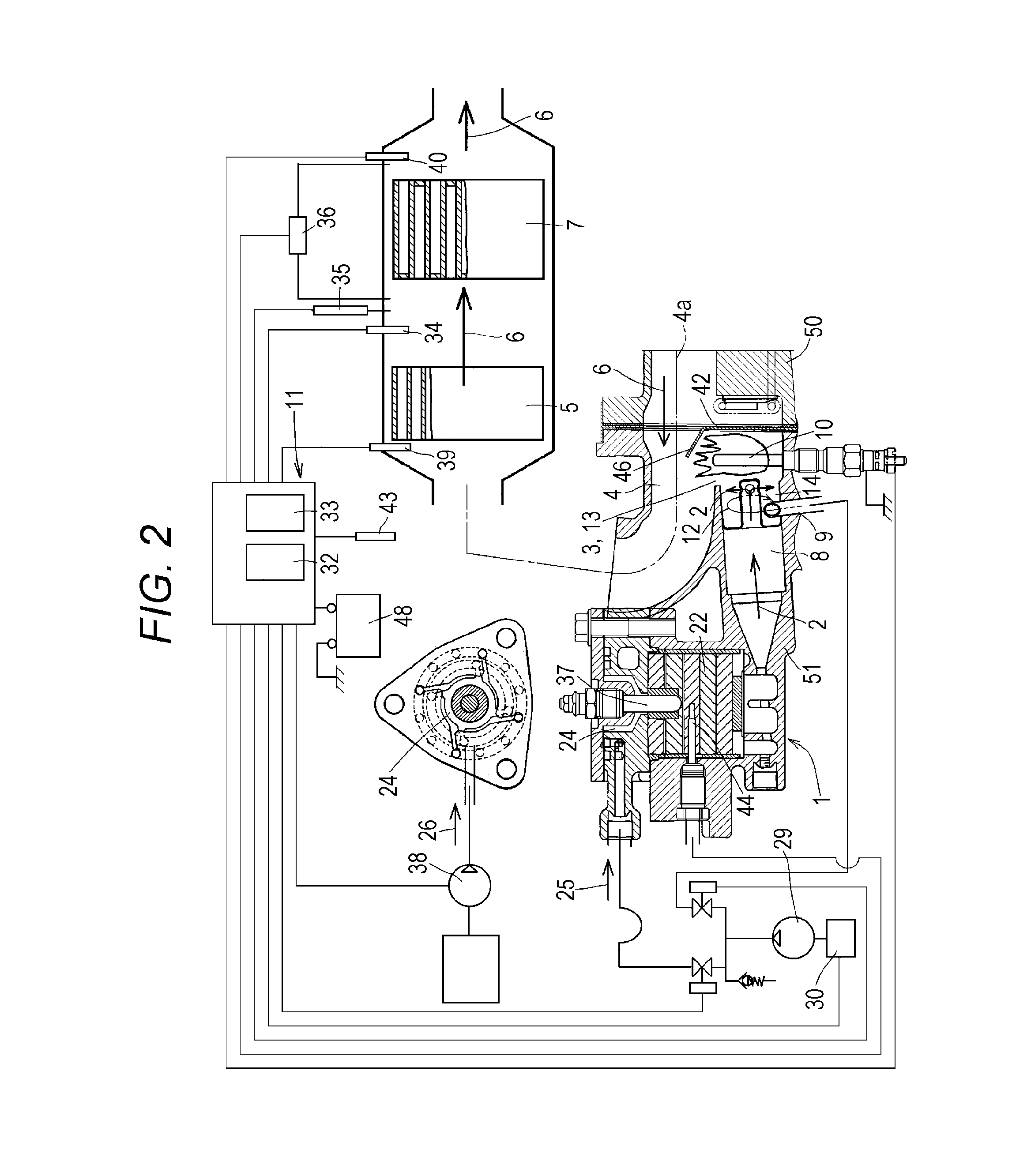
[0039]FIGS. 1A to 1C to FIG. 6 are diagrams for describing an exhaust treatment apparatus for an engine according to an embodiment of the present invention. In the present embodiment, a description will be given of an exhaust treatment apparatus for a diesel engine.

[0040]As shown in FIGS. 1A and 2, an oxidation catalyst (5) disposed in an exhaust passage (4), a combustible gas generator (1), and a combustible gas supplying passage (8) are provided.

[0041]The combustible gas supplying passage (8) is provided in parallel to and beneath the exhaust passage (4). A heat releasing port (13) is opened in an upstream side in the exhaust passage (4) from the oxidation catalyst (5) and in a downstream side in the combustible gas supplying passage (8). The exhaust passage (4) and the combustible gas supplying passage (8) communicate with each other through the heat releasing port (13). An ignition apparatus (10) is disposed beneath the heat releasing port (13). The heat of flaming combustion of...


PUM


Abstract

An exhaust treatment apparatus for an engine including a combustible gas supplying passage; a heat releasing port opened in an upstream side in the exhaust passage from the oxidation catalyst and in a downstream side in the combustible gas supplying passage, the exhaust passage and the combustible gas supplying passage communicating with each other through the heat releasing port; an ignition apparatus beneath the heat releasing port, the heat of flaming combustion of combustible gas ignited by the ignition apparatus being supplied to the exhaust passage to raise the temperature of exhaust in the exhaust passage; a flame holding plate in a downstream side in the combustible gas supplying passage from the ignition apparatus, an exhaust guiding plate at the top portion of the flame holding plate, the exhaust guiding plate having an upward slope toward a downstream side in the exhaust passage.

Description

BACKGROUND OF THE INVENTION[0001](1) Field of the Invention[0002]The present invention relates to an exhaust treatment apparatus for an engine. Specifically, the present invention relates to an exhaust treatment apparatus for an engine that can improve continuance of combustion flame of combustible gas.[0003](2) Description of Related Art[0004]A conventional exhaust treatment apparatus for an engine includes an oxidation catalyst disposed in an exhaust passage, a combustible gas generator, and a combustible gas supplying passage. The combustible gas supplying passage is disposed in parallel to and beneath the exhaust passage. A heat releasing port is opened in an upstream side in the exhaust passage from the oxidation catalyst and in a downstream side in the combustible gas supplying passage. The exhaust passage and the combustible gas supplying passage communicate with each other through the heat releasing port. An ignition apparatus is disposed beneath the heat releasing port. The...

Claims


Application Information

Patent Timeline
Patent Type & Authority Patents(United States)
IPC IPC(8): F01N3/10F01N3/025F01N3/36F01N3/32
CPCF01N3/10F01N3/36F01N3/0256F01N3/323F01N3/38F01N3/28
Inventor OKUDA, MITSUGUTAKEMOTO, YOSHIKAZUONISHI, TAKASHIISHIDA, HOZUMIMIYAZAKI, MANABUTAMAKI, YUICHIAKITOMO, TOMOYAARAI, KATSUAKI
Owner KUBOTA LTD
Why Eureka
Try Eureka