Passive-matrix display and tiling display

a technology of matrix display and tiling display, which is applied in the direction of identification means, instruments, semiconductor devices, etc., can solve the problems of increasing the surface area of the contour, and achieve the effect of reducing the distance from the connection portion of each second electrode to the farthest point to be reduced, and increasing the quantity of connection locations

Active Publication Date: 2016-01-19
SAMSUNG DISPLAY CO LTD
View PDF16 Cites 2 Cited by
  • Summary
  • Abstract
  • Description
  • Claims
  • Application Information

AI Technical Summary

Benefits of technology

[0011]A passive-matrix display pertaining to an aspect of the disclosure has a plurality of second electrodes and a plurality of second auxiliary electrodes arranged in parallel thereto. Accordingly, a configuration is realized in which the second electrodes and the second auxiliary electrodes are electrically connected via second connection portions each disposed with at least one of the first electrodes therebetween.
[0012]According to this configuration, increasing the quantity of connection locations in comparison to Patent Literature 1, in which there is only one connection location, enables the distance from the connection portion on each second electrode to the farthest point to be reduced. Thus, the wiring resistance is reduced in each of the second electrodes, which enables the drop in voltage and the variation in brightness to be reduced.
[0013]As such, according to the passive-matrix display pertaining to an aspect of the disclosure, a passive-matrix display and a tiling display are provided in which the drop in voltage caused by wiring resistance is constrained, and the variation in brightness is averaged out.

Problems solved by technology

Thus, the surface area of the contour is increased, which poses a problem in that the whole is not perceived as a single display.

Method used


Image

  • Passive-matrix display and tiling display
  • Passive-matrix display and tiling display
  • Passive-matrix display and tiling display

Examples


embodiment

Overall Configuration

Tiling Display

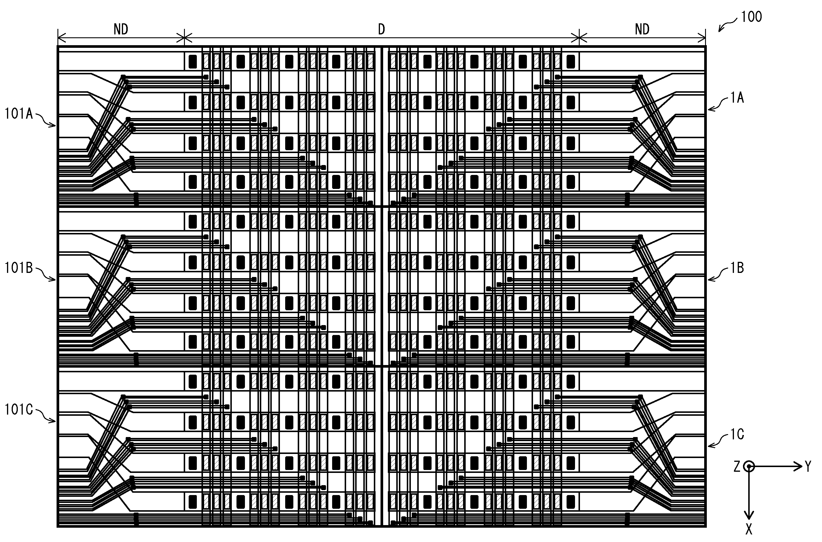
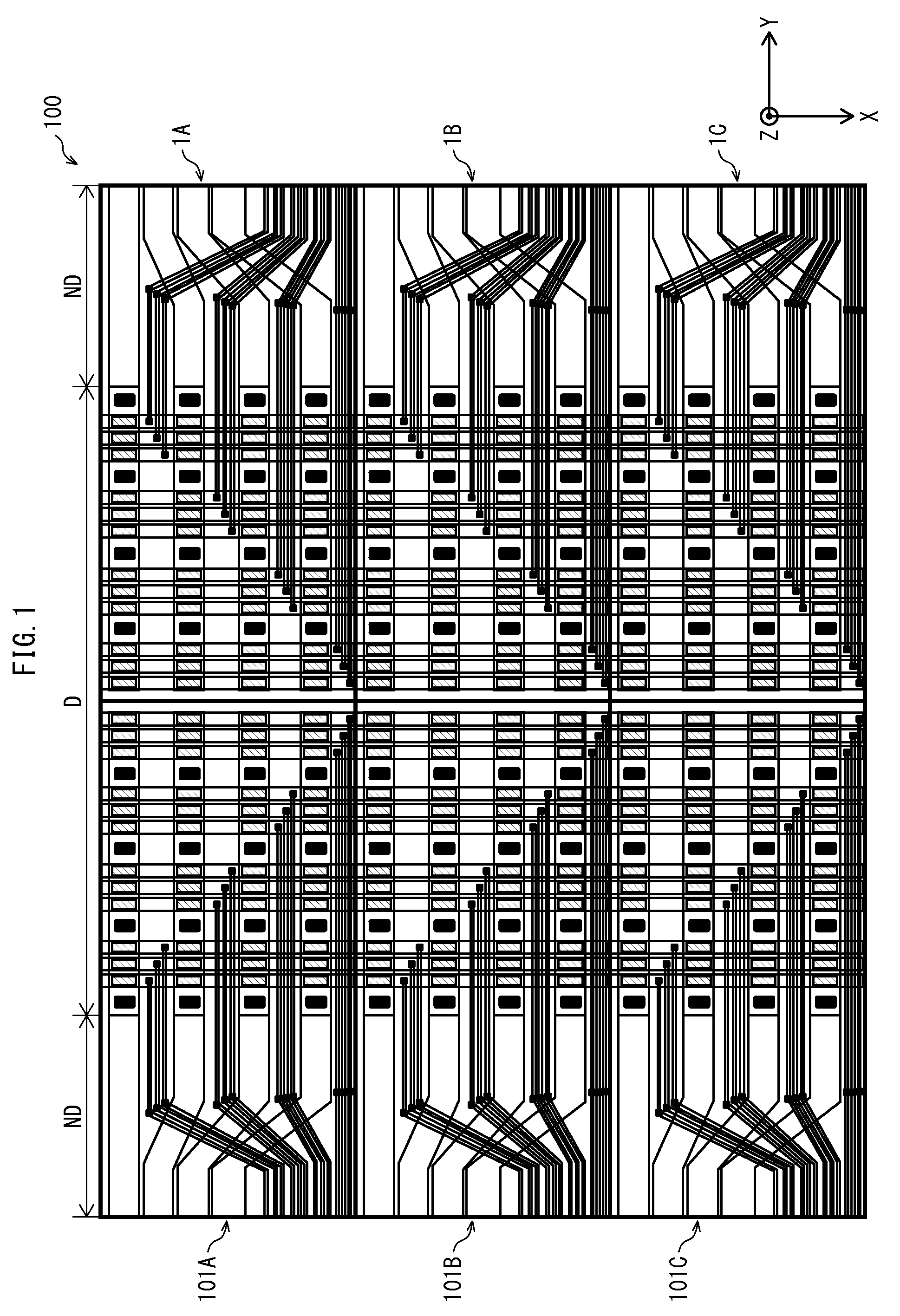
[0036]First, a tiling display 100 pertaining to the Embodiment is described with reference to FIG. 1. The tiling display 100 is shown as a total of six aligned displays, including passive-matrix displays 1A, 1B, and 1C and passive-matrix displays 101A, 101B, and 101C manufactured with line symmetry with respect to the X-axis of the other displays.

[0037]Region D of FIG. 1 indicates a display region having a periphery at an outermost edge of the light-emitting layer, and regions ND indicate non-display regions, each made up of a signal retrieval unit, neighbouring the display region. The signal retrieval units are thus disposed at one end along the Y-axis, in a unidirectional wiring configuration that enables the non-display region ND to be arranged at the ends of the display with respect to the Y-axis. As a result, the display regions D of the six displays are perceived as being one display, enabling the realization of a display for large-scale digi...


PUM


Abstract

A passive-matrix display of the disclosure includes a first electrode disposed over a substrate, a second electrode disposed over the first electrode and three-dimensionally intersecting the first electrode, a first auxiliary electrode disposed between the substrate and the first electrode, three-dimensionally intersecting the first electrode and being parallel to the second electrode, and a second auxiliary electrode parallel to the first auxiliary electrode and to the second electrode, the first electrode and the first auxiliary electrode being electrically connected by a first connection portion, and the second electrode and the second auxiliary electrode being connected by a plurality of second connection portions each disposed with at least one of the first electrodes therebetween. The passive-matrix display enables voltage drop and variation in brightness to be reduced by lowering the wiring resistance of the second electrode.

Description

TECHNICAL FIELD[0001]The present disclosure pertains to a passive-matrix display and to a tiling display making use thereof.BACKGROUND ART[0002]In recent years, tiling displays have been developed in which a plurality of passive-matrix displays are combined for use in large-scale digital signage, and such displays are spreading.[0003]Organic electroluminescence display 800 is an example of a conventional passive-matrix display for use in a tiling display. FIG. 9A shows a plan view and FIG. 9B shows a cross-sectional view taken along line A-A. The conventional organic electroluminescence display 800 includes a plurality of first electrodes 802 disposed as stripes over the first substrate 801 and a plurality of second electrodes 804 disposed as stripes that three-dimensionally intersect the first electrodes 802. An organic electroluminescence layer 806 is provided at each intersection between the first electrodes 802 and the second electrodes 804, and an insulating layer 803 is provid...

Claims


Application Information

Patent Timeline
Patent Type & Authority Patents(United States)
IPC IPC(8): H01L29/18G09F9/30G09F9/40H01L27/32H01L51/52
CPCH01L27/3288G09F9/30G09F9/40H01L27/329H01L27/3281H01L27/3283H01L27/3293H01L51/5212H01L51/5215H10K59/1795H10K59/179H10K50/814H10K50/816H10K59/17H10K59/18H10K59/173
Inventor IIJIMA, HIROAKIARAI, YASUHIRO
Owner SAMSUNG DISPLAY CO LTD
Why Eureka
Try Eureka