Edgecard connector with common-end datum to reduce misalignment tolerances

a technology of common end and connector, applied in the direction of connection, electrical apparatus, coupling device connection, etc., can solve the problems of loss of contact and/or shorting to adjacent pads, misalignment problems, and manufacturing tolerances limiting the pitch of edgecard pads, etc., to reduce or prevent misalignment tolerances and small contact pitch

Active Publication Date: 2016-03-29
SAMTEC
View PDF6 Cites 0 Cited by
  • Summary
  • Abstract
  • Description
  • Claims
  • Application Information

AI Technical Summary

Benefits of technology

[0012]To overcome the problems described above, preferred embodiments of the present invention provide an edgecard connector with a biasing mechanism that significantly reduces or prevents misalignment tolerances between contacts in the edgecard connectors and pads on the edgecard and that achieves a small contact pitch capable of being used with edgecards that have been manufactured without tight tolerances.

Problems solved by technology

Manufacturing tolerances limit how small the pad pitch of an edgecard can be.
This misalignment can result in loss of contact and / or shorting to the adjacent pad.
This float contributes to the misalignment problems.
However, this increases the cost of manufacturing the edgecards and edgecard connectors.

Method used


Image

  • Edgecard connector with common-end datum to reduce misalignment tolerances
  • Edgecard connector with common-end datum to reduce misalignment tolerances
  • Edgecard connector with common-end datum to reduce misalignment tolerances

Examples


Embodiment Construction

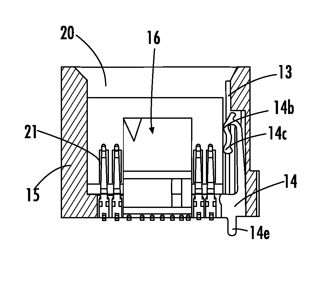
[0035]Preferred embodiments of the present invention are shown in FIGS. 10-33. Instead of having a centered ideal float, the connectors according to the preferred embodiments of the present invention have the ideal float aligned with one of the edges of the slot in the connector by biasing the edgecard to one side of the connector. This will be referred to as “edge aligned.”

[0036]Preferred embodiments of the present invention preferably use different biasing mechanisms to align the edgecard within the connector. It should be understood that other biasing mechanisms could be used as the biasing mechanism. The biasing mechanism preferably provides an increasing amount of force as the edgecard is inserted into the slot to help with insertion of the edgecard and to reduce the chance of rotating the edgecard due to unequal forces on the edges of the edgecard. The force of the biasing mechanism preferably increases as the edgecard is inserted into the slot to ensure that the edgecard is f...


PUM


Abstract

A connector includes a body, a slot within the body configured to receive a substrate and including a first end and a second end, contacts arranged along the slot between the first end and the second end, and a biasing mechanism arranged at the first end to align the substrate as the substrate is inserted into the slot so that substrate is in contact with the second end when the substrate is fully inserted into the slot.

Description

BACKGROUND OF THE INVENTION[0001]1. Field of the Invention[0002]The present invention relates to edgecards and edgecard connectors. More specifically, the present invention relates to edgecards and edgecard connectors with a biasing mechanism to reduce misalignment tolerances between contacts in the edgecard connectors and pads on the edgecards.[0003]2. Description of the Related Art[0004]Edgecards are typically manufactured from printed circuit boards (PCBs) and include surface pads that provide connection to electrical paths called traces on or within the edgecard. The edgecard is inserted into an edgecard connector so that the pads engage with the contacts in the edgecard connector to form a physical and an electrical connection. The distance between adjacent pads, i.e. pad pitch, on the edgecard is typically selected to be the same as the distance between adjacent contacts, i.e., contact pitch, in the edgecard connector.[0005]FIGS. 1 and 2 show an edgecard 200 inserted into a kn...

Claims


Application Information

Patent Timeline
Patent Type & Authority Patents(United States)
IPC IPC(8): H01R12/91H01R12/72
CPCH01R12/91H01R12/721
Inventor MONGOLD, JOHN, ALLENVICICH, BRIAN, R.KNOWLDEN, DONALD, CHRISTOPHER
Owner SAMTEC
Why Eureka
Try Eureka